A thin-wall aluminum part can measure correctly while it is clamped in the machine and still fail after removal.
The fixture may be holding a bowed blank flat. Cutting forces may temporarily push a wall away from the tool. Residual stress may be released as material is removed. Inspection support may then hold the finished part in a shape that it does not maintain in service.
For this reason, thin wall aluminum CNC machining is not only a question of spindle speed, feed rate, or machine accuracy. It is a shape-control problem that continues from stock selection through machining, unclamping, finishing, and final inspection.
Quick Answer
A stable thin-wall aluminum part requires control of four different conditions:
- The shape and residual-stress condition of the stock.
- The shape created by fixture forces.
- The temporary deflection caused by cutting force and heat.
- The released shape that will be inspected, assembled, and delivered.
The machining strategy should preserve stiffness while material is removed, avoid forcing the part into a false reference condition, and define whether final acceptance applies in a free state or a specified restrained state.
There is no universal wall-thickness number that makes every aluminum part “thin.” A wall becomes functionally thin when its stiffness is too low for the cutting, clamping, handling, finishing, or inspection forces applied to it.
A Wall Becomes Thin When Stiffness Controls the Process
A 1 mm wall on a small ring may behave differently from a 1 mm wall spanning a large enclosure. Wall height, unsupported length, corner geometry, floor thickness, ribs, openings, alloy condition, and fixture support can matter as much as nominal thickness.
For a rectangular section of width b and bending-direction thickness t, the centroidal second moment of area is: I=12bt3
Because bending rigidity depends on EI, reducing t can rapidly reduce the section’s resistance to bending. This relation is a useful directional model, not a complete prediction of a pocketed housing, ribbed enclosure, or locally supported wall.
A drawing should therefore be reviewed as a stiffness system rather than as a collection of independent dimensions. Two parts with the same minimum wall thickness may require completely different machining and inspection strategies.
Useful review questions include:
- How far does the wall span without support?
- Is the floor also thin?
- Does the wall connect to a rigid flange or return?
- Will openings interrupt the load path?
- Which features become flexible first as material is removed?
- Is the final functional condition free, bolted, clamped, or gasket-loaded?
One Part Can Have Four Different Shapes
The same workpiece can take different shapes during its manufacturing cycle.
| Part state | What controls the observed shape | Common interpretation error | Evidence needed |
|---|---|---|---|
| Stock state | Rolling, extrusion, heat treatment, stretching, sawing, storage, and initial residual stress | Assuming a visibly flat blank is internally stress-free | Stock form, temper, cutting orientation, initial flatness, and material condition |
| Clamped state | Locators, supports, jaw force, vacuum, bolts, and fixture contact | Treating a fixture-forced shape as the natural part shape | Clamp sequence, support map, contact condition, and unclamped comparison |
| Cutting state | Tool pressure, heat, chip evacuation, changing stiffness, and temporary vibration | Offsetting the program before identifying elastic deflection | Engagement, tool condition, wall direction, temperature, and in-process observations |
| Released and delivered state | Stress redistribution, spring-back, temperature, finishing, handling, and inspection support | Accepting the part from in-machine data alone | Free-state or defined restrained-state report, part temperature, and finish condition |
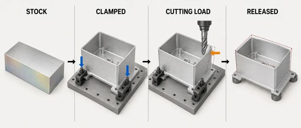
A process that controls only the clamped state can still deliver a nonconforming part.
The drawing, process plan, and inspection report should agree on which state represents the product requirement. If assembly intentionally restrains the part, that condition should be defined. It should not be recreated informally by pressing the component flat during inspection.
Diagnose What Is Moving Before Changing the Program
Dimensional drift does not always come from the same source. Adding a coordinate offset may hide one condition while making another worse.
| Observation | Possible mechanisms | Useful confirmation |
|---|---|---|
| Feature is correct while clamped but moves after release | Fixture preload, stock residual stress, unbalanced material removal, or thermal difference | Compare measurements before and after unclamping under a documented support condition |
| Wall thickness is stable but the wall profile is bowed | Elastic tool-force deflection or released part movement | Check thickness separately from profile and repeat after thermal stabilization |
| Error increases with wall height | Falling local stiffness, excessive radial load, tool runout, or long tool projection | Compare the error by height and review engagement and toolholder condition |
| Chatter begins after a pocket reaches a certain depth | Loss of temporary support, chip recutting, changing natural frequency, or unstable engagement | Identify the exact toolpath stage at which vibration begins |
| Shape changes after anodizing or another finish | Coating build, process temperature, racking, masking, or pre-existing stress redistribution | Compare the agreed pre-finish and post-finish inspection states |
| Two inspection methods disagree | Different supports, alignments, probe forces, filters, or feature-construction methods | Repeat the measurement using an agreed datum and support procedure |
A useful correction begins with a repeatable observation: when the movement appears, which direction it takes, and whether it remains after the load is removed.
Stock Condition Is Part of the Machining Strategy
“Alloy 6061” or “alloy 7075” does not completely define machining stability. Stock form, temper, thickness, cutting orientation, prior thermal history, and supplier processing also matter.
For applicable wrought products, T651 includes stress relief by controlled stretching after solution treatment. It may provide a more stable starting condition than an otherwise comparable T6 product, but it does not eliminate local stress or movement created by asymmetric machining.
The distinction between 6061-T6 and 6061-T651 should therefore be reviewed together with stock form and geometry, not used as a universal guarantee of flatness.
Material selection also should not be reduced to “6061 is stable and 7075 is unstable.” Strength, stock form, heat-treatment condition, section thickness, and the amount and distribution of removed material all affect the result. Material-specific risks for high-strength parts are discussed separately in the 7075 thin-wall CNC machining guide.
Before machining, confirm:
- Plate, bar, extrusion, forging, or another stock form.
- Temper and stress-relief condition.
- Rolling or extrusion direction where relevant.
- Initial stock flatness and thickness variation.
- Sawing allowance and thermal damage risk.
- Whether most material will be removed from one side.
- Whether the part can be re-established from a stable intermediate datum.
A thicker blank is not automatically safer. More stock can mean more material removal, more heat, and a larger redistribution of residual stress.
Preserve a Load Path as Material Disappears
The strongest version of the part usually exists before machining begins. Every pocket, opening, slot, and relief changes how cutting and clamping forces travel through the remaining material.
A suitable process may use staged roughing, temporary webs, sacrificial tabs, an onion skin, or balanced removal from interacting regions. These features are not goals by themselves. Their purpose is to keep the component supported until the remaining geometry can carry the next machining load.
For parts with significant release risk, the route may include:
- Establishing stable reference features.
- Roughing major cavities while leaving controlled material.
- Releasing or reducing fixture force to observe movement.
- Allowing the part to return to a consistent temperature.
- Re-establishing datums from the new part state.
- Semi-finishing critical walls and floors.
- Removing temporary support in a controlled sequence.
- Finishing the features that define final assembly.
Intermediate unclamping does not remove residual stress by itself. It reveals movement that the fixture may have been hiding and allows the next setup to reference the actual intermediate shape.
When opening a closed pocket, a circular or helical ramp can reduce abrupt engagement and improve chip evacuation compared with a full-width entry. Use it only when the cutter is ramp-capable and the cavity provides sufficient diameter and clearance; a predrilled opening or another controlled entry may be more suitable for restricted geometry.
The objective is a predictable load transition, not a mandatory CAM pattern.
Workholding Must Locate the Part Without Forcing It
A fixture has three related jobs:
- Locate the workpiece.
- Support the cutting load.
- Prevent movement during machining.
It should not force a flexible blank into the nominal CAD shape and then use that forced condition as proof of conformity.
Large contact areas can distribute load, but they can also copy debris, burrs, or stock waviness into the setup. Concentrated clamps can hold securely but may create local dents or bend a thin flange. Vacuum fixtures can provide distributed holding, but available area, seal condition, floor stiffness, leakage, and axial cutter force must be reviewed.
Useful thin-wall workholding practices may include:
- Supporting rigid regions instead of unsupported wall centers.
- Using fixture contacts that are accessible for cleaning and verification.
- Applying only the clamping force required to prevent movement.
- Keeping clamp locations and tightening sequence repeatable.
- Using soft jaws shaped around stable geometry.
- Avoiding excessive jaw closure on thin rings.
- Providing backup support where the cutter pushes toward the wall.
- Checking the part after clamp force is reduced or removed.
If the drawing requires a restrained inspection condition, the fixture should reproduce that condition deliberately. Clamp position, support location, torque, sequence, and temperature may all become part of the acceptance definition.
Tooling Strategy Is About Force Direction and Time in Cut
Tool selection affects more than surface finish. Cutter diameter, flute geometry, helix, edge preparation, runout, projection, radial engagement, axial engagement, and chip evacuation determine how the cutting load enters the wall.
Sharp cutting edges and suitable aluminum geometry may reduce rubbing and built-up edge, but “sharp” is not a complete specification. A cutter with excessive runout can load one flute disproportionately. A long projection may amplify both tool deflection and wall vibration. A very light pass may rub instead of forming a stable chip.
The aluminum milling cutter selection guide explains how cutter geometry, rigidity, chip space, and tool reach interact.
For a common up-cut end mill, increasing the helix angle may reduce radial loading while increasing the axial lifting component. This can help a tall wall but load a thin floor, weak vacuum fixture, or marginal toolholder in another direction.
Helix angle should therefore be selected with the cutter geometry, engagement, chip evacuation, wall orientation, floor stiffness, and workholding—not from one universal degree range.
The process should also limit sudden changes in engagement. Corner entry, slot opening, chip recutting, and abrupt direction changes can excite a flexible section even when the programmed feed appears conservative.
The Final Pass Cannot Correct a Moving Reference
A finish pass follows the programmed path, but the tool can only cut the surface position that exists under load.
If a wall deflects away during cutting, a repeated spring pass may reproduce the same loaded condition. If the pass becomes too light to form a stable chip, rubbing can add heat without correcting the geometry. Reducing feed alone may therefore fail to solve the underlying problem.
Before the final pass, confirm:
- The fixture is referencing a stable part state.
- Major residual-stress movement has already been exposed.
- Temporary supports are removed in the intended sequence.
- Tool runout and projection are appropriate.
- The wall and its connecting floor are finished in a compatible order.
- The part has not been heated significantly above the agreed inspection condition.
- Sufficient material remains to correct the measured intermediate shape.
A coordinate correction can be useful after the mechanism is known. It should not replace diagnosis.
Inspection Must Reproduce the Agreed Part State
Thin-wall inspection is part of the manufacturing strategy because the measuring method can change the shape being measured.
A CMM probe, bore gauge, micrometer, indicator, surface plate support, or fixture can apply enough force to move a flexible feature. The result may also change with point density, scanning direction, filter settings, datum alignment, and part temperature.
A CMM inspection plan for CNC-machined parts should therefore define more than the machine name.
| Inspection target | Suitable method | Main risk |
|---|---|---|
| Wall thickness | Micrometer, caliper, CMM, or suitable optical method | Contact squeeze, jaw alignment, or local wall tilt can alter the result |
| Wall profile or bow | CMM scanning, discrete probing, or optical measurement | Support, point density, filtering, and fitting method can change the reported profile |
| Thin ring bore or outside diameter | Bore gauge for ID, micrometer for OD, CMM, or a suitable optical method | The thin section may change shape under gauge contact, jaws, or probe force |
| Mating-face flatness | CMM or a surface plate with an indicator under a defined support condition | Excess support or clamping can suppress the free-state error |
| Bore location | CMM or an agreed functional method | Datum establishment and released part movement may dominate the result |
| Surface roughness | Profilometer with an appropriate setup | Stylus force, cutoff selection, and wall movement may affect the trace |
A restrained functional check and a free-state geometric inspection answer different questions. The drawing should identify which one controls acceptance.
Surface Finishing Can Change Fit, Not Repair Form
Anodizing, conversion coating, blasting, painting, and other finishes can affect dimensions, surface texture, contact areas, and inspection access.
Anodizing can change bore, slot, thread, and mating-surface dimensions depending on coating type, specified thickness, masking, and the location of the functional surface. These effects should be considered before the final machining dimensions are released.
The surface finishes for CNC-machined parts guide explains why finish requirements should be connected to function and tolerance.
Finishing should not be treated as a method for straightening a bowed wall. If the part is already distorted, coating the surface does not restore the datum system or correct released form.
The drawing or purchase requirement should identify:
- The finish specification and class where applicable.
- Masked and unmasked areas.
- Whether dimensions apply before or after finishing.
- Critical electrical, cosmetic, sealing, or mating surfaces.
- The inspection stage that controls final acceptance.
The Drawing Must Define the State, Not Only the Nominal Shape
A thin-wall drawing can be dimensionally complete and still leave the most important acceptance question unanswered: what condition must the part be in when those dimensions are verified?
| Drawing or RFQ item | What should be defined |
|---|---|
| Alloy and stock condition | Alloy, temper, preferred stock form when functionally important, and any traceability requirement |
| Critical thin features | Wall or floor thickness, unsupported span, height, openings, ribs, and transition geometry |
| Datum system | Functional datum features and whether they remain stable after release |
| Part state | Free-state requirement or the exact restrained assembly or inspection condition |
| Support condition | Support locations, fixture interface, fastener pattern, gasket condition, and torque where functionally required |
| Finishing state | Which dimensions apply before or after anodizing, coating, blasting, or another finish |
| Mating function | Sealing face, bearing seat, cover interface, optical alignment, or other relationship that controls acceptance |
| Inspection communication | Report scope, sampling, feature IDs, and the agreed acceptance condition |
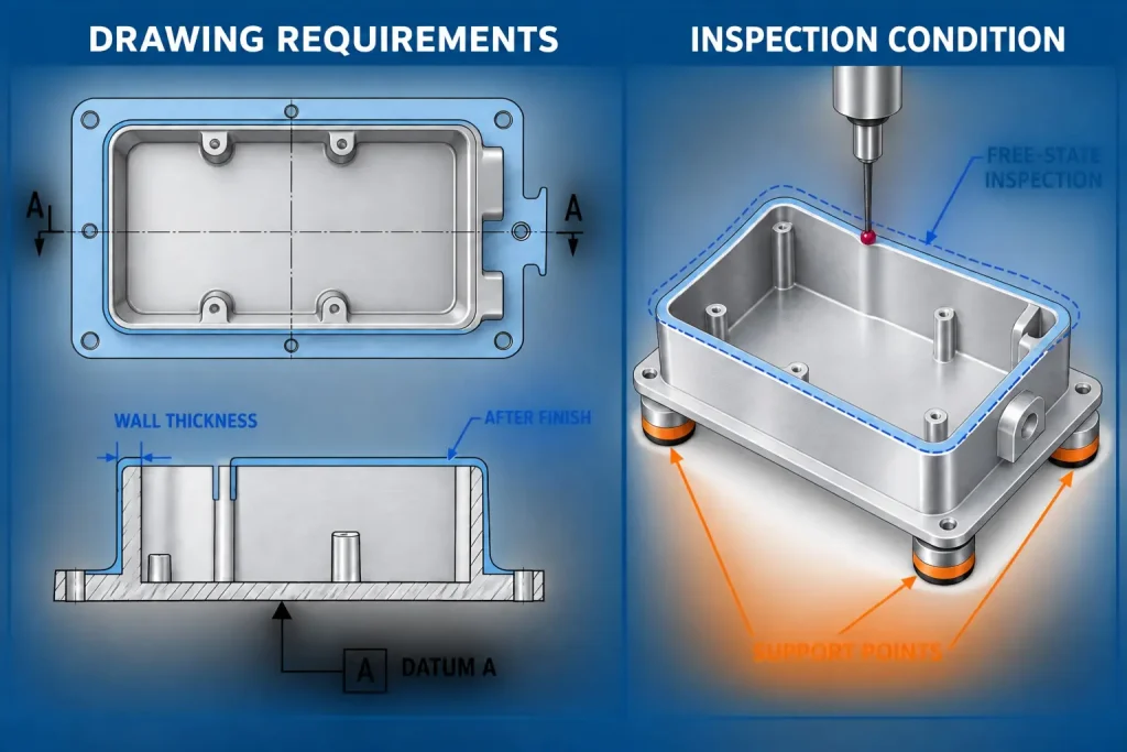
The drawing does not need to dictate every cutter or fixture detail. It should define the functional result and the state in which that result must exist.
General size tolerances alone may not control bow, flatness, profile, perpendicularity, or feature location. The relationship between dimensional and geometric requirements is explained in the CNC machining tolerances guide.
Why Less Material Can Cost More to Machine
A lightweight part uses less material in the finished condition, but it may require more controlled manufacturing time.
Cost can increase because of:
- Additional roughing and semi-finishing stages.
- Temporary material that is removed later.
- More conservative engagement near flexible features.
- Custom soft jaws, vacuum fixtures, or distributed support.
- Intermediate unclamping and datum re-establishment.
- Longer-reach tooling or additional access setups.
- More detailed inspection of free and restrained states.
- Increased deburring and handling sensitivity.
- Pre-finish and post-finish dimensional verification.
- Higher process-development and rejection risk.
The main cost driver is often not the nominal wall thickness alone. It is the combination of wall thickness, unsupported span, removed volume, datum stability, surface finish, inspection state, and required repeatability across the batch.
When a Design Change Is More Effective Than a Process Change
Some deformation risks can be reduced more effectively by changing the load path than by making the machining cycle slower.
| Possible design change | Potential effect | Review condition |
|---|---|---|
| Add a return flange | Increases edge stiffness | Check mass, envelope, assembly access, and finishing |
| Add or reposition ribs | Shortens unsupported span | Check tool access, corner radii, chip evacuation, and stress concentration |
| Increase local wall thickness | Adds stiffness where movement begins | Confirm that the added material does not interfere with function |
| Increase internal corner radius | Supports a larger, stiffer cutter and improves load transfer | Check mating geometry and required clearance |
| Reduce wall height | Decreases leverage and vibration sensitivity | Confirm functional envelope |
| Move large openings away from flexible edges | Preserves a stronger load path | Check airflow, cable, optical, or assembly requirements |
| Separate critical datum features from flexible walls | Improves inspection and setup stability | Confirm that the datum still represents assembly function |
The correct choice depends on what the wall must do. A sealed enclosure, optical frame, heat-transfer surface, motor housing, and cosmetic cover may require different compromises.
Review a Thin-Wall Aluminum Part Before Quotation
For a useful thin-wall review, provide:
- 3D CAD and the controlled 2D drawing.
- Aluminum alloy, temper, and preferred stock form if already specified.
- Minimum wall and floor thicknesses.
- Major unsupported spans and wall heights.
- Critical bores, sealing faces, bearing seats, and mating interfaces.
- Required free-state or restrained-state acceptance condition.
- Datum and support requirements.
- Surface finish and whether dimensions apply before or after finishing.
- Inspection-report and sampling requirements.
- Prototype and expected production quantities.
RapidEfficient can review the relationship between stock condition, workholding, machining sequence, finishing, and inspection before quotation. For suitable projects, this review can be coordinated through our CNC aluminum machining services.