A machined pocket can have a smooth wall and a small measured variation, yet still fail its profile requirement. The wall may sit on the wrong side of the allowed boundary.
A unilateral profile tolerance places the entire tolerance zone on one side of the true profile. The true profile forms one boundary of that zone. The surface may vary within the permitted region, but it cannot cross the opposite boundary.
This matters when a surface must protect clearance, preserve material, or stay outside a mating part’s space. Reading the total tolerance is only the first step. The drawing and inspection program must also agree on which side is allowed.
The examples below use surface profile and the ASME circled-U modifier, shown as Ⓤ. Always apply the standard and edition specified on the drawing.
Read the Total Width Before the Ⓤ Value
The true profile is the theoretically exact shape defined by the drawing or model. For an ordinary equally disposed profile tolerance, half the total zone width lies on each side of that shape.
The ASME Ⓤ modifier changes this distribution:
- The number before Ⓤ gives the total tolerance-zone width.
- The number after Ⓤ gives the portion outside the theoretical material boundary.
- The remaining portion lies inside the theoretical material boundary.
“Outside the material” means the direction in which the actual surface would add material. It does not mean a fixed direction on the drawing sheet. PTC’s documentation on unequally disposed profile tolerances illustrates this distinction with a zone extending 0.10 outside the material and 0.20 inside it.
For the calculations below, define a local surface deviation d:
- Positive d: more material than the true profile.
- Negative d: less material than the true profile.
Let t be the total tolerance and u the value after Ⓤ. At a smooth surface location, the permitted normal deviation is:
u − t ≤ d ≤ u
For 0.30 Ⓤ 0.10, the lower limit is 0.10 − 0.30 = −0.20 mm, and the upper limit is +0.10 mm. Negative deviation means less material; positive deviation means more material.
The following examples use millimeters. The notation shows only the tolerance-value portion of a feature control frame; a complete drawing also needs the proper profile symbol, controlled extent, and any required datum references.
| Tolerance-value notation | Permitted deviation d | Distribution |
|---|---|---|
0.30, equally disposed | −0.15 to +0.15 mm | Equal bilateral |
0.30 Ⓤ 0.10 | −0.20 to +0.10 mm | Unequal bilateral |
0.30 Ⓤ 0 | −0.30 to 0 mm | Unilateral; less material allowed |
0.30 Ⓤ 0.30 | 0 to +0.30 mm | Unilateral; more material allowed |
Both unilateral cases keep the same 0.30 mm total width; only the permitted side changes.
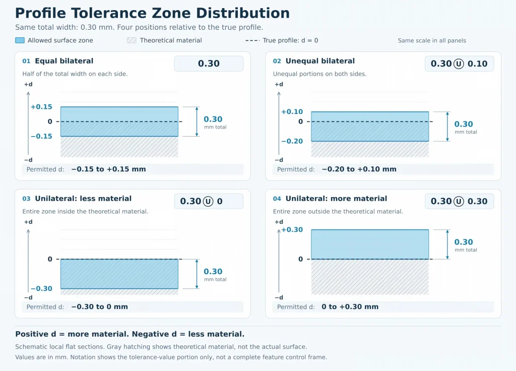
Two reading errors can change the result completely. The value after Ⓤ is not extra tolerance, so 0.30 Ⓤ 0.10 does not create a 0.40 mm zone. It is also not the zone-center offset. In that example, the midpoint is −0.05 mm.
An unequal zone is not necessarily unilateral. The 0.30 Ⓤ 0.10 example still allows variation on both sides of the true profile.
An Internal Pocket Reverses the Size Effect
Apply the material-side rule to an external boss and an internal pocket.
On an external boss, adding material makes the boss larger. A 0.30 Ⓤ 0 zone permits the controlled surface to move into the theoretical solid, allowing a smaller external shape within the stated limits.
On an internal pocket, adding material makes the opening smaller. The same 0.30 Ⓤ 0 zone permits the wall to move into the surrounding solid, allowing a larger opening.
The rule has not changed. The location of the material has changed.
This is why a sketch should show the material side, preferably with section hatching. Labels such as “inside,” “outside,” “positive,” or “negative” can become unclear when the drawing changes from an external contour to a cavity.
Also, the profile value is not automatically a hole-diameter or slot-width tolerance. Opposing walls have different local normal directions. Their combined effect on opening size must be worked out from the actual geometry and applicable controls.
For limits applied directly to a size dimension, see the bilateral vs unilateral tolerance guide. A one-sided size tolerance and a unilateral profile tolerance are different drawing requirements.
A Small Deviation Range Can Still Fail
Consider the 0.30 Ⓤ 0 example again. Assume the drawing and its datum references fix the position and orientation needed for this evaluation.
The permitted signed deviations are:
−0.30 mm ≤ d ≤ 0 mm
Now compare three illustrative sets of measured surface points.
| Minimum deviation | Maximum deviation | Maximum minus minimum | Comparison with the permitted zone |
|---|---|---|---|
| −0.24 mm | −0.03 mm | 0.21 mm | Sampled points are within both limits |
| −0.20 mm | +0.02 mm | 0.22 mm | Exceeds the zero boundary by 0.02 mm |
| −0.33 mm | −0.08 mm | 0.25 mm | Exceeds the negative boundary by 0.03 mm |
All three ranges are smaller than 0.30 mm, but only the first set stays between both boundaries.
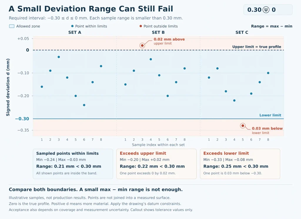
The range describes the spread of the measured deviations. It does not show where that spread sits relative to the true profile. A surface can therefore have little variation and still occupy a forbidden region.
These are geometric examples, not production inspection results. Final acceptance also depends on measurement uncertainty and the agreed decision rule.
Keep the required datum constraints
A best fit must preserve the constraints imposed by the drawing. It cannot freely move the measured surface until the result looks acceptable.
Where the datum system leaves certain movements free, suitable optimization may be allowed. The important question is which movements remain available—not whether a software option happens to contain the words “best fit.”
Check what the reported number means
A CMM may report signed deviations, a single profile result, or a color map. These displays do not always use the same reference.
Confirm whether deviations are measured from the true profile or from the shifted zone center.
For 0.30 Ⓤ 0, the limits are −0.30 to 0 mm when the true profile is zero. If the zone center at −0.15 mm is used as zero, the same limits are −0.15 to +0.15 mm. A point at +0.02 mm from the true profile is +0.17 mm from that center. It exceeds the same physical boundary in either format.
Hexagon’s PC-DMIS documentation on surface profile describes evaluation around a defined zone center, subject to datum constraints. It also shows how insufficient sampling can understate the actual surface error.
For a useful report, identify the controlled surface, datum references, zone limits, sign convention, and inspected area. Sampling should cover likely problem regions, including wall transitions, deep sections, and areas affected by tool deflection.
The CMM inspection guide for CNC-machined parts explains how to connect drawing requirements with measurement coverage and reporting.
Keep the Design Surface and the Cutting Target Separate
With a unilateral zone, the true profile lies at a limit. Cutting exactly to that surface leaves no margin toward the prohibited side.
The manufacturing target therefore needs a separate decision. Mitutoyo’s explanation of ASME Y14.5-2018 notes that an as-designed dimension does not automatically establish a manufacturing target.
For the illustrative interval from −0.30 to 0 mm, the midpoint is −0.15 mm. That may be a useful starting point for process planning. It is not a drawing requirement or a universal cutting target. Tool behavior, remaining operations, functional needs, and measurement uncertainty can affect the choice.
Keep the released design model as the nominal inspection reference. If CAM uses a separate offset model, record its offset and revision. Check which model the CMM program uses before applying the drawing’s profile requirement.
A double-offset error can occur when an already shifted manufacturing surface is treated as the original true profile and the same zone disposition is applied again. An offset CAM model and a correctly configured CMM program can work together without this error.
On a curved surface, a constant normal offset also differs from moving the entire model along X, Y, or Z. A global translation cannot generally reproduce a profile-zone offset around a complex contour.
Before calculating the toolpath, confirm that the CAM offset moves the surface toward the intended material side. Check local radii, adjoining faces, and tool access on the offset geometry. Verify the simulated cut against both profile-zone boundaries, using the released design model as the reference.
Include finishing in the same decision
A coating can add material to the controlled surface. Polishing or other removal operations can move it in the opposite direction.
Specify whether the profile requirement applies before or after finishing. Then plan the machining allowance around the expected effect and variation of that process. Do not treat the whole finishing operation as a single guaranteed offset.
Review the relevant surface finishes for CNC-machined parts together with the profile requirement. The wider CNC machining tolerances guide can help place this feature within the part’s overall tolerance budget.
For a unilateral zone with a zero upper limit, placing the average surface at nominal can leave roughness peaks or burrs beyond that limit. Consider these features when choosing the process target. Ra alone does not define the highest peak, and a CMM scan may not capture every small surface feature.
ASME Ⓤ and ISO UZ Use Different Numbers
ASME Ⓤ and ISO UZ can both describe a zone that is not centered on the true profile, but their numbers have different meanings.
The ASME value specifies the portion outside the material. ISO UZ specifies a signed offset of the zone center.
For example, ISO 0.30 UZ+0.15 places the center 0.15 mm outside the material. Its 0.30 mm zone therefore extends from 0 to +0.30 mm.
Do not replace Ⓤ with UZ while keeping the same number. Check the governing standard and the resulting physical boundaries before entering the requirement into CAD or inspection software.
Agree on the Boundary Before Machining
Before releasing a unilateral profile requirement, make sure the drawing, model, and inspection plan describe the same permitted surface.
The handoff should resolve five points:
- Which standard and edition apply? State the governing interpretation.
- Which surface is controlled? Define its extent and identify the material side.
- Where are the two zone boundaries? Confirm the total width and its distribution.
- What fixes the zone to the part? Include the required datum references and basic geometry.
- Which condition is accepted? State whether inspection applies after machining, finishing, or another specified operation.
For a CNC part with this requirement, send the feature control frame, released CAD model, datum scheme, and finishing notes through our precision machining services page.
Include the mating feature or a short explanation of the clearance being protected. That gives the machining review a clear task: establish the allowed side, choose a suitable process target, and plan inspection against the same boundaries.