锪孔与沉头孔: 设计紧固件座, 不仅仅是深度

锪孔面与沉头孔的决定不仅仅与深度有关. Both features may appear as a larger coaxial diameter with a flat bottom around a smaller hole, but they solve different assembly problems.

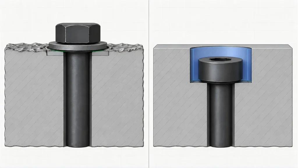
一个 spotface creates a controlled bearing surface for a bolt head, 坚果, 垫圈, 夹钳, or other component. 一个 counterbore creates a controlled cylindrical recess for a fastener head, 垫圈, plug, or another defined envelope.

Depth follows the assembly requirement.

Choose a spotface when the joint needs a usable seating surface on a rough, 弯曲, 投掷, 锻造的, 焊接的, 涂层, or otherwise unsuitable starting surface. Choose a counterbore when the hardware must enter the part to a controlled position. If the joint needs both a complete bearing land and a recessed head, the drawing must control both functions.


The Decision Is Not “Shallow or Deep”

A counterbore can be relatively shallow, and a spotface can require more material removal than expected. Applying an arbitrary depth limit can therefore classify the feature incorrectly.

Start with the result the assembly must achieve.

Decision factorSpotface沉头孔
Primary functionProduce a usable bearing or contact surfaceProvide a cylindrical envelope for hardware
Typical starting condition粗糙的, 弯曲, drafted, 涂层, or locally uneven surfaceMachined or unmachined material that must receive a fastener head
Diameter logicBased on the required head, 垫圈, 坚果, or clamp bearing landBased on head or washer diameter, driver access, 清除, and available material
Depth logicEnough cleanup to achieve the specified bearing condition, unless a fixed depth is requiredControlled by the required head position and available material
Expected hardware positionThe head or washer may remain above the surrounding surfaceThe head or other component enters the recess
Main rejection riskA visibly machined area that does not provide the required bearing landA head that sits too high, contacts a corner, or leaves insufficient wall.
Cross-section comparison of a washer on a shallow spotface and a recessed socket-head screw seated in a counterbore

A drawing should not call the feature a spotface merely because it is shallow. It should not call it a counterbore merely because a counterbore cutter was used.


Read the Fastener Stack from the Outside In

The feature cannot be designed from the nominal screw diameter alone. Read the entire stack from the accessible side of the assembly:

  1. Driver and installation-tool access
  2. Fastener-head diameter and height
  3. Washer outside diameter and thickness, if used
  4. Under-head fillet, 倒角, or formed transition
  5. Machined bearing surface
  6. Clearance or threaded hole
  7. Remaining wall and nearby cavities
  8. Backside nut, 插入, 螺纹啮合, or exit condition

A washer can require a larger bearing diameter than the screw head. A driver may need more radial clearance than the installed fastener. An under-head transition can contact an uncontrolled edge before the nominal bearing surface reaches the seat.

Tool access must be matched to the actual hardware. An internal-hex socket-head screw normally uses a hex key or driver bit inserted into the head. A recessed external-hex bolt normally requires a socket that fits around the head, so the socket outside diameter may control the recess.

Deep counterbores can create another constraint. Even when the bit itself fits, the bit holder, extension, automated tightening spindle, or other installation equipment may be too large to enter the recess. Counterbore diameter should therefore not be selected from head diameter plus a generic clearance allowance.

For inch-series socket screws, ASME B18.3 provides dimensional data and related information for socket screws, keys, bits, and counterbore sizes. The actual purchased fastener and assembly tool still need to be confirmed.

The hole definition also matters. A process label does not replace the finished-feature requirements, as explained in the 螺纹孔与螺纹孔导轨. The drawing still needs to define the usable thread, 清除, 深度, and assembly interface.

Before selecting either feature, answer these questions:

  • Is the head allowed to remain proud of the surrounding surface?
  • Must it be nominally flush or below the surface?
  • Is a washer mandatory, 选修的, or prohibited?
  • Which actual fastener standard and size will be installed?
  • Does assembly use a hex key, driver bit, socket, wrench, or automated spindle?
  • Must the tool enter the recess, or only the fastener?
  • Will coating, 电镀, 画, or conversion treatment change the final interface?
  • Is there enough wall beneath and around the proposed recess?

A Continuous Bearing Land Defines the Spotface

A spotface is valuable when the original surface cannot distribute clamp load reliably.

Common examples include cast bosses, forged surfaces, structural fabrications, drafted faces, curved housings, and parts with local coating buildup. The cutter removes high points and creates a controlled local seat around the hole.

The required diameter should be based on the real contact member—not only the nominal bolt size. If a washer is used, the seat must support it without allowing the loaded area to overhang an edge, casting draft, adjacent pocket, or interrupted surface.

Depth requires more careful language than “spotface as required.” Depending on the design, the drawing may need one or more of the following:

  • A fixed depth from a defined reference surface
  • Cleanup until a complete bearing land is achieved
  • A minimum acceptable bearing width
  • A requirement for full circumferential cleanup
  • A maximum material-removal limit
  • A minimum remaining-wall requirement
  • A combination of cleanup and maximum depth

A bright circular tool mark is not proof of acceptable bearing contact. A narrow cleaned arc can look finished while leaving part of a washer supported by the original uneven surface. Similar appearance-versus-function risks occur on larger machined faces, as discussed in the face milling surface guide.

The sequence relative to finishing must also be explicit. A spotface machined before coating may carry the final coating unless the seat is masked or re-machined. A spotface machined after coating normally exposes the substrate in the cut area. The drawing should define the required final seat condition because either route can change corrosion, 接地, 摩擦, or cosmetic behavior.


The Head Envelope Defines the Counterbore

A counterbore must accommodate an actual component envelope.

For a socket-head screw, this normally includes head diameter, head height, 尺寸变化, under-head transition, 装配间隙, driver access, 涂层厚度, and the corner geometry left by machining.

Counterbore depth should be related to the intended head position:

  • Proud of the surrounding surface
  • Nominally flush
  • Below the surface by a defined amount
  • Recessed only far enough to provide guarding or tool clearance

“Flush” should not be assumed to mean perfect geometric equality under every tolerance condition. The drawing should establish an allowable position or range if head projection affects sealing, 包装, 安全, 外貌, 或干扰.

Two different transition areas require review.

The first is the inner transition around the fastener shank. The fastener’s under-head fillet may interfere with a sharp clearance-hole entrance or an unsuitable washer inside diameter.

The second is the outer transition between the counterbore wall and floor. A tool-generated bottom radius may interfere with the lower outside edge of the head or washer.

Either condition can prevent the intended bearing surface from reaching the counterbore floor. A torque wrench may reach the specified installation torque even though geometric interference has prevented complete seating or reduced the intended clamp load. Installation torque alone is therefore not proof that the head is fully supported.

The drawing may need to define a hole-entry chamfer, corner relief, permissible bottom radius, or compatible washer geometry. These requirements should be based on the actual fastener and tool, rather than a universal edge-break rule.

The designer must also check the remaining wall below the recess. A deeper counterbore can weaken a thin flange, approach an internal cavity, expose porosity in a casting, or break through a backside surface.


Cast Surface Variation Can Consume the Spotface Allowance

Raw-surface variation changes both manufacturing risk and drawing interpretation.

Suppose a spotface depth is measured from the original cast surface. Variation in that surface can produce different final seat locations relative to the functional datums. If the depth is instead fixed from a machined datum, the cutter may fail to clean the highest parts of the casting.

The drawing and RFQ should therefore identify:

  • The surface from which depth is measured
  • The expected stock or casting variation
  • Whether full cleanup is mandatory
  • The deepest permissible cleanup
  • The minimum wall that must remain
  • Whether final seat position or complete bearing contact has priority

Spotfaces and counterbores can be produced by overlapping machining methods. Depending on geometry, 使用权, 数量, 和宽容, a supplier may consider a piloted tool, circular interpolation with an end mill, boring and facing, or a backside spotfacing method.

This process overlap reinforces an important rule: the cutter does not define the feature—the assembly function does.

Back spotfacing introduces its own access problem. The tool passes through an existing hole and cuts the opposite surface, often in an area that cannot be observed directly. An enclosed cavity can make chip evacuation, 冷却剂输送, cutter deployment, seat protection, and tool withdrawal more difficult.

The cutter-opening mechanism depends on the selected tool. It may use coolant pressure, compressed air, a manual mechanism, centrifugal action, or another tool-specific method. The drawing should not assume that every back-spotfacing tool requires the same spindle direction or deployment sequence.

报价前, the supplier may need to confirm:

  • Pilot-hole diameter
  • Backside cutter clearance
  • Available cavity depth
  • Blade or cutter deployment space
  • Chip and coolant path
  • Risk of trapped chips marking the seat
  • Tool retraction and withdrawal conditions

If backside access creates excessive process risk, the designer and supplier may review a different fastener arrangement, insert strategy, split construction, or another geometry appropriate to the project.

Backside access, 断断续续的剪辑, large diameters, 薄壁, 困难的材料, and tight orientation requirements can materially affect the process plan. These conditions should be reviewed during quotation for 数控铣削服务, rather than discovered after the toolpath has been released.

Manufacturing conditionLikely effect
Uneven cast bossVariable cleanup depth and interrupted cutting
Backside bearing seatAdditional access, chip-control, cutter-deployment, or specialized-tooling requirements
Large recess near a thin wallHigher distortion and breakthrough risk
Tight relation to a datum axisMore controlled setup and inspection
Machining after coatingExposed material and added handling requirements
Mandatory complete cleanupGreater dependence on the incoming stock envelope

Drawing Callouts Must Separate Function from Toolpath

A drawing should communicate the required finished condition, not merely suggest a machining operation.

The spotface or counterbore symbol must be interpreted under the drawing standard and edition required by the contract. ASME Y14.5 establishes drawing symbols, rules, definitions, and interpretation practices, but a copied symbol cannot replace missing functional requirements.

Do not rely on an old drawing convention, a 3D model color, or a shop note such as “spotface as required” when depth, cleanup, 壁厚, or head position affects acceptance.

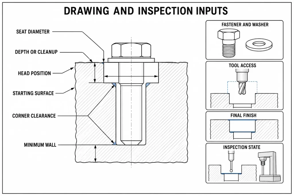
Drawing itemSpotface decisionCounterbore decisionRisk if omitted
Feature purposeBearing or contact requirementRecessed component envelopeSupplier optimizes the wrong function
Associated hole清除, 线, 插入, or other feature清除, 线, 插入, or other featureFastener stack does not assemble
直径Required bearing area and edge clearanceHead, 垫圈, driver, and process clearanceOverhang or radial interference
DepthFixed depth, cleanup rule, 或两者兼而有之Head position and required recess depthVariable seating or projection
Fastener definitionHead, 垫圈, 坚果, or clamp interfaceActual head and washer envelopeNominal screw size is insufficient
Installation accessTool type and required working space少量, socket, 持有者, extension, or automated spindle clearanceFastener fits but cannot be installed
Starting surface投掷, 锻造的, 弯曲, 涂层, or machinedSurface used as the depth referenceDepth is measured from the wrong surface
Final finish stateBefore or after coating, 掩蔽, 或重新加工Before or after coating, 掩蔽, 或重新加工Final fit or contact condition changes
Position and orientationApply when the bearing interface requires themApply when head clearance or assembly requires themSeat and hole do not share the intended relationship
Bottom transitionHole-entry relief and bearing-edge requirementsClearance for head fillet, 垫圈, and tool radiusHardware contacts an edge before seating
Remaining materialMinimum wall or cleanup limitMinimum floor or sidewall thicknessBreakthrough or local weakness
检验条件Define final state and required evidenceDefine final state and required evidenceSupplier and buyer inspect different functional states.
Spotface and counterbore drawing guide showing fastener selection, 工具访问, seat diameter, 深度, 壁厚, 结束, 和检查

Tolerance values should follow the assembly risk rather than a generic machining default. 这 CNC加工公差指南 explains why function, process sequence, and inspection method must be considered together.


Inspection Must Test the Intended Interface

Spotface and counterbore inspection should answer different functional questions.

Functional questionPossible evidenceMisleading shortcut
Does the spotface provide the required bearing land?Defined cleanup extent, dimensional measurement, surface scan, or functional contact checkAccepting any visible circular tool mark
Is the spotface diameter sufficient?卡尺, optical system, CMM, or another suitable methodMeasuring only the cutter or programmed toolpath
Is counterbore depth correct?Depth measurement, height comparison, CMM, or functional assemblyAssuming tool Z position equals final depth
Will the head reach its intended position?Actual or controlled representative fastener and washerChecking only nominal recess diameter
Can the assembly tool reach the fastener?Tool-envelope model, controlled representative tool, or assembly trialChecking the fastener without its driver
Is there inner or outer corner interference?Profile evaluation, suitable probing, contact check, 或功能性贴合Ignoring the under-head fillet and bottom radius
Is the feature correctly related to the hole or datum?CMM or another method matched to the specified controlUsing visual concentricity alone
Is sufficient wall left?Dimensional inspection from controlled referencesSubtracting nominal dimensions without verifying the part
Is the final finish state acceptable?Inspection after the required coating or post-processInspecting only the unfinished machined part

No single instrument proves every requirement. A depth micrometer may verify an accessible depth but not coaxiality. A CMM may evaluate location and surface geometry but still require an appropriate probing strategy. A functional screw can reveal interference but does not automatically quantify every drawing characteristic.

同样地, reaching the specified installation torque does not prove that the head, 垫圈, or nut has complete bearing contact. When seating is functionally critical, the inspection plan should include suitable geometric or functional evidence.

Inspection should occur in the specified final condition. 毛刺去除, 涂层厚度, paint buildup, 部分约束, 温度, and the selected measurement reference can all change the reported result.


Fastener-Seat Functional Decision Matrix

Use this matrix as a starting point before releasing the drawing. The final choice still depends on the actual geometry, 硬件, 加载中, 结束, tooling access, 及检验要求.

Starting conditionAssembly goalStarting feature choiceRequirements that still need definitionMain risk
Rough cast boss with a washerDistribute clamp load on a usable seatSpotfaceBearing diameter, cleanup rule, maximum depth, remaining wallPartial cleanup or excessive material removal
Flat machined plate with an exposed bolt headProvide a normal clearance-hole jointPossibly neither孔径, 表面状况, head clearanceAdding an unnecessary operation
Socket-head screw must sit below the surfaceCreate controlled head clearance沉头孔Head standard, 直径, 深度, head position, corner clearanceHead projection or bottoming
Rough casting with a recessed headProvide both bearing cleanup and a head envelopeCounterbore with explicit cleanup requirements基准参考, complete cleanup, head position, wall limitOne requirement passes while the other fails
Deep recess used with automated tighteningPermit both fastener seating and tool entryCounterbore after tool-envelope reviewDriver body, holder diameter, insertion depth, withdrawal pathFastener fits but assembly tool cannot enter
Thin flange near an internal cavityAssemble without breakthroughGeometry review before either featureMinimum floor, cavity position, alternative head styleWeak floor or breakthrough
Seat required on an inaccessible backsideSupport a nut, 垫圈, or clampBack spotface or revised designAccess, cutter deployment, chip path, land diameter, 毛刺控制专用工装, 困屑, or incomplete cleanup
Coated housing with a functional contact seatControl seating and final surface stateDepends on required head position加工顺序, 掩蔽, exposed material, finish condition, 检查状态腐蚀, 合身, or contact changes after finishing

Release the Feature Only After These Inputs Agree

A useful RFQ should provide more than a nominal hole diameter. Include:

  • The 3D model and controlled drawing
  • Fastener designation and applicable standard
  • Head and washer requirements
  • Installation tool or automated tightening equipment
  • Allowed head position
  • Spotface or counterbore diameter
  • Fixed-depth, cleanup, or combined requirement
  • Original surface type and expected variation
  • Final coating, 掩蔽, or surface-treatment state
  • Permissible hole-entry and bottom-corner geometry
  • Minimum remaining wall
  • Nearby cavities, 边缘, and interference zones
  • Backside access and chip-evacuation constraints
  • 基准, 位置, or orientation requirements
  • Burr and edge conditions
  • 检查方法, 报告, or functional evidence required
  • 原型和生产数量

根据项目要求, RapidEfficient can review the hole geometry, fastener stack, installation-tool envelope, 加工通道, 完成序列, 以及报价前的检验要求.

The objective is to determine whether the part needs a bearing spotface, a recessed counterbore, requirements for both functions, or a simpler feature that avoids unnecessary machining.

发表评论

滚动至顶部

获取报价

点击或拖拽文件到该区域即可上传. 您最多可以上传 10 文件.
文件格式:TXT PDF DOC DOCX XLS XLSX PPT PPTX JPG PNG ZIP RAR DWG DXF DXF DWT DWS DWS

3D文件格式: 步, STP, sldprt, IPT, prt, 坐着, IGES, IGS, catpart, X_T, OBJ, STL