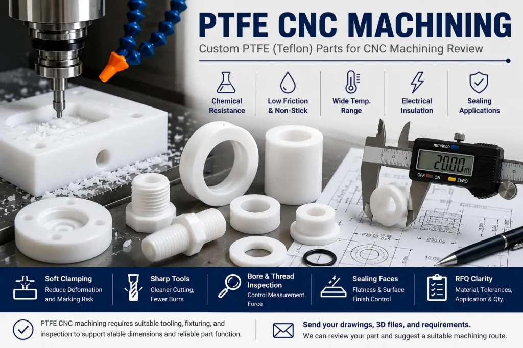
PTFE CNC machining is not difficult because the material is hard.
It is difficult because PTFE is soft, slippery, flexible, and easy to deform during clamping, cutting, inspection, and assembly.
A metal part may stay stable after machining. A PTFE part may move slightly when it is held, released, measured, pressed into assembly, or exposed to temperature change.
This is why PTFE CNC parts need a different review process from aluminum, stainless steel, brass, or PEEK parts.
A good PTFE machining plan should review:
- material grade
- wall thickness
- part stiffness
- clamping method
- tool sharpness
- burr control
- thread design
- bore tolerance
- sealing faces
- surface finish
- inspection method
- final application
- quantity and repeatability
PTFE is often selected for low friction, chemical resistance, sealing, insulation, and non-stick behavior. But those same properties can also make machining, fixturing, and inspection more sensitive.
The goal is not to avoid PTFE.
The goal is to design PTFE machined parts in a way that matches the real behavior of the material.
What Is PTFE CNC Machining?
PTFE CNC machining is the process of cutting PTFE stock into custom parts using CNC milling, CNC turning, drilling, boring, tapping, grooving, or secondary machining operations.
PTFE is also commonly searched as Teflon, although Teflon is a brand name. In RFQs, buyers may write:
- PTFE parts
- Teflon parts
- PTFE machined parts
- PTFE CNC machining
- CNC Teflon machining
- PTFE bushings
- PTFE seals
- PTFE insulating parts
- PTFE spacers
- PTFE sleeves
- PTFE valve seats
PTFE can be machined into many custom parts, but it does not behave like a rigid engineering plastic.
Compared with POM, nylon, acrylic, or PEEK, PTFE usually needs more attention to clamping pressure, dimensional stability, thread strength, and inspection condition.
For a broader material comparison, see our Best Plastics for CNC Machining guide.
Why PTFE Machines Differently from Metals
Many CNC machining problems come from one simple mistake:
The buyer or supplier treats PTFE like aluminum.
That can create problems.
PTFE is much softer and more flexible than most metals. It can move under clamping force, spring back after cutting, and deform under measurement pressure.
| PTFE Behavior | Machining Effect |
|---|---|
| Low stiffness | Thin walls and long features can bend during cutting |
| Low friction | Workholding can be less stable if clamping is not planned |
| Soft cutting behavior | Burrs and edge deformation can occur if tools are dull |
| High flexibility | Measured dimensions may change after unclamping |
| Thermal sensitivity | Dimensions may shift with machining heat or inspection temperature |
| Low surface energy | Coating, bonding, or marking may need special review |
| Creep under load | Press fits, threads, and loaded features need caution |
| Excellent chemical resistance | Good for seals, insulators, fluid-contact parts, and chemical equipment |
PTFE stock produced by molding or extrusion may contain internal stress from the stock manufacturing process. When a machining process removes material unevenly, especially during heavy roughing, deep pocketing, or one-sided milling, the stress balance inside the part can change.
This can cause long, thin, or asymmetrical PTFE features to move slightly after unclamping or after a stabilization period. The part may look acceptable during machining, but the final shape may shift before final inspection or assembly.
For complex or tight-tolerance PTFE parts, the supplier may review balanced material removal, staged roughing and finishing, a short stabilization period, or stress-relief conditioning when required. This is especially important for thin sleeves, long strips, large pockets, sealing faces, and parts with uneven wall thickness.
PTFE can produce excellent custom parts, but the process must respect the material.
For general CNC material and process support, see our CNC machining services page.
When PTFE Is a Good CNC Material
PTFE is often a good choice when the part needs low friction, chemical resistance, electrical insulation, or sealing behavior.
Common PTFE machined parts include:
| Part Type | Why PTFE May Be Used |
|---|---|
| Bushings | Low friction and wear behavior in selected applications |
| Sleeves | Good sliding and insulating behavior |
| Seals | Chemical resistance and sealing function |
| Valve seats | Chemical resistance and low friction |
| Spacers | Electrical insulation and chemical stability |
| Washers | Low friction and non-stick behavior |
| Gaskets | Sealing and chemical compatibility |
| Lab equipment parts | Chemical resistance |
| Semiconductor fixture parts | Insulation and chemical resistance, depending on application |
| Fluid system parts | Resistance to many chemicals |
| Electrical insulating components | High insulation value |
| Wear pads | Low friction in selected contact conditions |
PTFE is useful when the part function depends on the material itself.
It is less suitable when the main requirement is high stiffness, sharp thin features, very tight threads, or rigid press-fit behavior.
When PTFE May Not Be the Best Choice
PTFE is not always the best engineering plastic.
Before choosing PTFE, the buyer should check whether the application really needs its low friction, chemical resistance, or temperature behavior.
PTFE may need extra review when the part has:
- very thin walls
- long unsupported features
- tight press fits
- small internal threads
- sharp edges
- high clamping load
- high assembly force
- tight positional tolerance
- small deep holes
- cosmetic surface requirements
- load-bearing features
- mating parts that apply continuous pressure
- inspection requirements similar to metal parts
In some cases, POM, PEEK, nylon, PEI, PPS, or another engineering plastic may be more suitable.
For example, POM may be better for many general precision plastic parts, while PEEK may be better for demanding temperature, strength, or stability needs. For more context, see our PEEK vs POM CNC machining comparison.
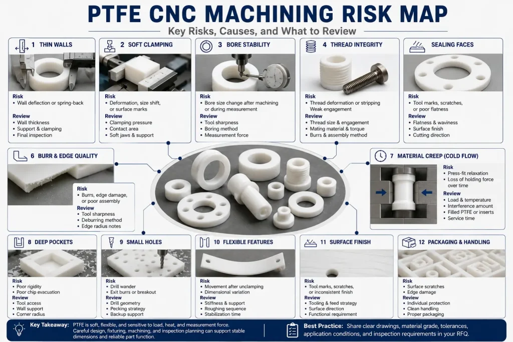
PTFE Machining Risk Map
PTFE machining risk usually appears in a few feature types.
| Feature | Main Risk | What to Review |
|---|---|---|
| Thin walls | Wall deflection or spring-back | Wall thickness, support, clamping pressure, final inspection |
| Small bores | Size shift after machining | Tool sharpness, boring method, inspection pressure |
| Threads | Weak or distorted thread form | Thread size, engagement length, mating part, assembly load |
| Press fits | Creep and deformation | Load, temperature, assembly force, long-term contact |
| Sealing faces | Tool marks or waviness | Flatness, surface finish, cutting direction, inspection method |
| Deep pockets | Poor rigidity and chip control | Tool access, wall support, corner radius |
| Long sleeves | Ovality or taper | Soft jaws, support, turning setup, inspection location |
| Sharp corners | Burrs and edge damage | Edge radius, deburring method, functional edge notes |
| Small holes | Drill wander or burrs | Hole depth, drill geometry, pecking, backup support |
| Cosmetic surfaces | Handling marks | Packaging, glove handling, surface protection |
This risk map helps prevent a common RFQ mistake: asking for metal-like tolerances without explaining how the PTFE part will be held, used, and measured.
Tolerance Planning for PTFE CNC Parts
PTFE tolerance should be reviewed more carefully than aluminum or stainless steel tolerance.
A tight number on the drawing does not always mean the part will hold that number in real use.
Tolerance depends on:
- part size
- wall thickness
- material grade
- stock condition
- machining heat
- clamping pressure
- tool sharpness
- inspection temperature
- measurement force
- feature stiffness
- final application
- quantity and repeatability
Small, thick, well-supported PTFE features are usually easier to control than thin, flexible, long, or unsupported features.
A bore in a thick PTFE block may be more stable than a thin PTFE sleeve with the same nominal diameter.
A flat sealing face may be easier to control when the part is well supported during machining and inspection.
For general tolerance planning, see our CNC machining tolerances guide.
Clamping and Fixturing Are Critical
PTFE can deform if clamping force is too high.
This is one of the biggest differences between PTFE and metal machining.
If the part is squeezed during machining, the cutter may machine the compressed shape. After the part is released, it can recover slightly and the final measured dimension may change.
Common clamping risks include:
| Clamping Issue | Possible Result |
|---|---|
| Too much vise pressure | Part distortion or size shift after release |
| Small contact area | Local dents or surface marks |
| Poor support under thin areas | Chatter, wall movement, or uneven thickness |
| Unstable round stock holding | Ovality or taper |
| Hard jaws on soft material | Visible clamping marks |
| Over-tightened internal mandrel | Bore distortion |
| No backup support during drilling | Exit burrs or breakout |
For PTFE parts, soft jaws, custom fixtures, light clamping, larger contact areas, and staged machining may be needed.
The fixture does not need to be complicated for every project. But it should match the part stiffness and tolerance requirement.
Tooling for PTFE Machining
PTFE usually cuts best with sharp tools and a controlled cutting strategy.
Dull tools can push the material instead of cutting it cleanly. This can create burrs, rough edges, poor size control, or surface tearing.
Tooling review may include:
- sharp cutting edges
- polished tool surfaces
- suitable rake angle
- controlled tool engagement
- proper chip clearance
- light finishing cuts
- reduced heat buildup
- stable tool support
- correct drilling strategy
- deburring method
The goal is not maximum cutting speed.
The goal is clean cutting with minimal pushing, dragging, heat, and distortion.
For milled PTFE parts with pockets, slots, holes, and machined faces, see our CNC milling services page.
CNC Turning PTFE Parts
PTFE is often turned into bushings, sleeves, rings, washers, spacers, seals, and valve seats.
Turning PTFE can look simple, but round parts can still have issues:
- ovality
- taper
- poor bore stability
- thin-wall deformation
- thread distortion
- surface marks from jaws
- parting burrs
- inspection variation
For PTFE rings and sleeves, the supplier should review the relationship between outer diameter, inner diameter, wall thickness, and clamping method.
If the wall is thin, the part may need soft jaws, light chuck pressure, internal support, or a modified process route.
For custom rotational parts, see our CNC turning services page.
Threads in PTFE Need Extra Review
PTFE threads need more caution than metal threads.
The material is softer, so small internal threads, short engagement length, or high assembly force can create problems.
Possible PTFE thread issues include:
- thread deformation
- loose engagement
- cross-threading risk
- burrs at thread start
- weak thread crests
- poor repeatability after repeated assembly
- size change after tapping
- damage from metal mating parts
Thread design should consider:
| Thread Factor | Why It Matters |
|---|---|
| Thread size | Very small threads may be fragile |
| Engagement length | Short threads may not hold load well |
| Mating material | Metal screws can damage PTFE threads if over-tightened |
| Assembly torque | High torque can deform the thread |
| Insert requirement | Some designs may need metal inserts instead of direct PTFE threads |
| Inspection method | Thread gauges may apply force and affect results |
| Burr control | Entry and exit burrs can affect assembly |
If a PTFE part needs repeated assembly, the design should be reviewed before production.
A metal insert, larger thread, longer engagement, or design change may be more reliable than forcing a small direct thread into PTFE.
PTFE Bores, Sleeves, and Bushings
PTFE bores and sleeves are common, but they can be sensitive.
A PTFE bushing may look simple on the drawing, but machining and inspection can be affected by:
- wall thickness
- chuck pressure
- bore depth
- length-to-diameter ratio
- tool pressure
- material relaxation
- measurement force
- final assembly fit
- temperature condition
Another mechanical behavior to review is cold flow, also known as creep under sustained load. PTFE can slowly deform under continuous clamping, compression, or assembly pressure, even when the part is used at normal room temperature.
This matters for PTFE bushings, sleeves, valve seats, seals, and press-fit features. If a PTFE bushing is pressed tightly into a metal housing, the material may relax over time and the holding force or bore size may change.
For applications with sustained load, tight press fits, or repeated assembly, the supplier may review filled PTFE grades, longer engagement length, reduced interference, metal inserts, or a different plastic material. The best choice depends on load, temperature, mating material, service time, and inspection requirements.
For bushings, the buyer should define whether the bore is:
- a clearance bore
- a sliding bore
- a sealing bore
- a bearing surface
- a press-fit feature
- a guide feature
- an insulation feature
These different functions need different tolerance and surface review.
A tight bore tolerance may be reasonable for a thick, short bushing. The same tolerance may be risky for a long, thin sleeve.
Sealing Faces and Surface Finish
Many PTFE parts are used as seals, valve seats, gaskets, or fluid-contact components.
For these parts, the sealing face may matter more than the overall appearance.
A sealing face should be reviewed for:
- flatness
- waviness
- tool marks
- scratches
- burrs
- edge damage
- surface direction
- mating surface
- compression load
- final cleaning
- packaging protection
Surface finish notes should be realistic.
A drawing note that only says “smooth surface” is not enough for a sealing feature.
Better drawing notes may include:
- which face is sealing
- whether scratches are acceptable
- whether tool marks must be controlled
- whether surface roughness is required
- whether flatness is functional
- whether the part will be compressed in assembly
- whether leak testing or functional checking is needed
For broader finish planning, see our CNC surface finishes guide.
Thin Walls and Flexible PTFE Features
Thin PTFE walls can move during machining.
They may also move after the part is released from the fixture.
This can affect:
- wall thickness
- flatness
- roundness
- bore size
- hole position
- sealing face contact
- visual surface quality
- assembly fit
For thin-wall PTFE parts, the supplier should review:
| Review Item | Why It Matters |
|---|---|
| Wall thickness | Thin PTFE walls are more likely to deflect |
| Unsupported height | Tall features can vibrate or bend |
| Clamping position | Poor support can distort the feature |
| Roughing sequence | Uneven material removal can release stress |
| Finishing allowance | A light final cut may improve size control |
| Inspection timing | The part may relax after unclamping |
| Measurement force | Soft material can deform under contact measurement |
| Packaging | Soft surfaces can be marked during shipment |
A thin-wall PTFE part may still be machinable, but the tolerance should match the feature stiffness.
Filled PTFE vs Virgin PTFE
Not all PTFE materials machine or perform the same way.
Some PTFE grades include fillers such as glass fiber, carbon, graphite, bronze, or other additives.
Filled PTFE may be selected to improve wear resistance, stiffness, thermal behavior, or dimensional stability, depending on the application.
However, filled PTFE can also affect:
- tool wear
- surface finish
- edge quality
- burr behavior
- color
- friction behavior
- inspection stability
- material cost
- mating surface wear
The RFQ should clearly state whether the part requires virgin PTFE or a filled PTFE grade.
Do not assume the supplier can choose the grade only from the word “Teflon.”
A material note should include the exact grade, color, filler, certificate requirement, and any application condition that affects material choice.
PTFE Machining and Heat
PTFE can be sensitive to heat during machining and inspection.
Machining heat may come from:
- tool friction
- dull cutting edges
- poor chip removal
- heavy tool pressure
- continuous cutting
- insufficient cooling strategy
- aggressive drilling or tapping
PTFE also has high thermal expansion compared with many common CNC materials, and its dimensional behavior can be affected by temperature changes near normal room conditions. Some PTFE grades may show small dimensional changes around room-temperature transition ranges, so inspection temperature can matter more than buyers expect.
If a precision PTFE feature is machined in a warm shop environment and then measured immediately in a cooler inspection area, the measured size may shift slightly after the part stabilizes. For tight-tolerance PTFE features, the supplier may review whether the part needs cooling time, temperature stabilization, or final inspection under a consistent measurement condition.
The goal is not to make every PTFE project complicated. The goal is to avoid accepting a dimension that only looks correct under a temporary thermal condition.
Heat can make dimensional control more difficult.
A part may measure one way immediately after cutting and another way after it returns to a stable condition.
For tight PTFE features, the supplier may review whether the part needs cooling time before final inspection.
The goal is not to make every PTFE project slow.
The goal is to avoid accepting a dimension that only looks correct under a temporary machining condition.
Inspection Challenges for PTFE CNC Parts
PTFE inspection can be tricky because the material is soft.
The measurement method itself can affect the result.
Inspection issues may include:
| Inspection Issue | Possible Problem |
|---|---|
| High contact force | Soft feature may compress during measurement |
| Thin-wall bore measurement | Bore may deform under gauge pressure |
| Flexible part handling | Shape may change depending on support |
| Immediate inspection after machining | Heat or stress may not be stable |
| Different inspection setups | Results may vary between shop and customer |
| Thread gauge force | Thread may deform during checking |
| Surface scratch sensitivity | Handling can create marks after inspection |
| Unclear datum references | Soft part may be hard to align consistently |
For critical PTFE parts, the drawing should define what dimensions are critical and how they should be inspected.
A CMM report may be useful for some features, but contact pressure, support, datum alignment, and inspection condition still need review.
For inspection planning, see our CMM inspection for CNC parts guide.
PTFE Machining Tolerance Should Match Function
Not every PTFE dimension needs the same tolerance.
A good PTFE drawing separates:
- functional dimensions
- reference dimensions
- cosmetic edges
- sealing faces
- clearance holes
- flexible walls
- assembly-critical features
- non-critical external shapes
This helps the supplier focus machining and inspection effort where it matters.
| Feature Type | Tolerance Review |
|---|---|
| Sealing face | Flatness, surface condition, and compression behavior matter |
| Clearance hole | May not need tight tolerance |
| Press-fit feature | Needs caution due to creep and deformation |
| Thread | Needs engagement and assembly review |
| Bushing bore | Roundness, measurement force, and final fit matter |
| Thin wall | Tolerance should reflect stiffness |
| Cosmetic edge | Burr and handling control may matter more than dimension |
| Insulation spacer | Function may depend on thickness and hole location |
Do not apply tight tolerances across the whole drawing unless every feature truly needs them.
This can increase cost and inspection difficulty without improving part function.
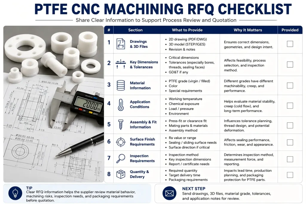
RFQ Checklist for PTFE CNC Machining
Before requesting a PTFE CNC machining quote, provide information that helps the supplier review material behavior and process risk.
| RFQ Item | What to Provide |
|---|---|
| 2D drawing | Dimensions, tolerances, datums, notes, surface finish, and critical features |
| 3D model | STEP / STP / IGES / X_T file |
| Material grade | Virgin PTFE or filled PTFE grade |
| Color | Natural white, black, or specified color if required |
| Quantity | Prototype, low-volume batch, or repeat production |
| Critical features | Bores, threads, sealing faces, thin walls, press fits, or sliding surfaces |
| Mating parts | Shaft, screw, housing, metal insert, seal, or assembly contact |
| Surface finish | Ra value, visual standard, sealing face requirement, or scratch limit |
| Thread requirement | Thread size, engagement length, mating screw, and assembly torque if known |
| Fit requirement | Clearance, sliding fit, press fit, or functional gap |
| Inspection requirement | CMM, gauge, bore measurement, thread gauge, visual inspection, or report |
| Application condition | Chemical exposure, temperature, load, friction, sealing, or insulation |
| Post-processing | Cleaning, deburring, marking, packaging, or assembly |
| Delivery target | Helps review process route and inspection timing |
A good RFQ does not only say “PTFE part.”
It explains which features must function correctly after machining, inspection, shipping, and assembly.
Practical Drawing Notes for PTFE Parts
Example 1: Sealing Face
Marked face is functional sealing surface. Supplier to review flatness, tool marks, scratches, and packaging protection before production.
This is better than only writing “smooth finish.”
Example 2: Thin-Wall Sleeve
Thin-wall sleeve requires light clamping and final bore inspection after unclamping. Supplier to review roundness and measurement method.
This helps reduce disagreement between machining and inspection results.
Example 3: PTFE Thread
Internal thread is for light assembly only. Supplier to review thread engagement, burr control, and mating screw before machining.
This avoids treating PTFE threads like metal threads.
Example 4: Filled PTFE Grade
Material: carbon-filled PTFE, black. Supplier to confirm exact grade, certificate requirement, and machining allowance before production.
This prevents grade substitution.
Example 5: Press-Fit Feature
Press-fit area requires application review. PTFE creep and assembly load should be confirmed before final tolerance selection.
This is important because PTFE can deform under long-term pressure.
Packaging and Handling for PTFE Machined Parts
PTFE surfaces can be marked or scratched during handling.
Packaging should be reviewed when the part has:
- sealing faces
- cosmetic surfaces
- polished or smooth areas
- thin edges
- small threads
- precision bores
- soft contact surfaces
- cleanroom or fluid-contact requirements
Possible packaging steps include:
- individual wrapping
- soft separators
- protective bags
- clean handling
- edge protection
- avoiding heavy stacking
- marking orientation for critical surfaces
- separating metal and plastic parts
Packaging does not improve machining accuracy, but it helps protect the condition achieved during machining and inspection.
Rapid Efficient Support for PTFE CNC Machining
Rapid Efficient can review custom PTFE CNC machined parts according to material grade, geometry, tolerance, surface requirement, and inspection needs.
We can review:
- PTFE material grade
- virgin or filled PTFE requirement
- CNC milling or turning route
- thin-wall risks
- bore and sleeve stability
- thread design
- sealing faces
- clamping method
- burr control
- surface finish
- inspection method
- packaging needs
- prototype or low-volume production plan
For prototype and small-batch custom parts, see our low-volume CNC machining services page.
If your PTFE part has threads, thin walls, sealing faces, tight bores, or press-fit features, send the 2D drawing, 3D model, material grade, quantity, and application notes before quotation. We can review the part and suggest a suitable machining route.
Buyer Questions About PTFE CNC Machining
Is PTFE easy to CNC machine?
PTFE can be cut with CNC equipment, but it is not always easy to control. The material is soft and flexible, so clamping, tool sharpness, burr control, and inspection method matter.
Is PTFE the same as Teflon?
PTFE is the material name. Teflon is a well-known brand name often used in search and buyer RFQs. For manufacturing, the drawing or RFQ should specify the exact PTFE grade, filler, and certificate requirement if needed.
Can PTFE hold tight tolerances?
PTFE can hold controlled dimensions on suitable features, but tight tolerance depends on part geometry, wall thickness, clamping, material grade, machining heat, and inspection method. Thin or flexible features need extra review.
Can PTFE parts have threads?
Yes, PTFE parts can have threads, but thread size, engagement length, mating screw, assembly torque, and repeated assembly should be reviewed. Small or highly loaded PTFE threads may need design changes or inserts.
Is PTFE good for bushings and sleeves?
PTFE can be used for bushings and sleeves when low friction, chemical resistance, or insulation is needed. Bore size, roundness, wall thickness, and inspection pressure should be reviewed carefully.
What files should I send for PTFE CNC machining?
Send a 2D drawing, 3D model, material grade, filler requirement, quantity, critical features, tolerance notes, surface finish requirements, mating parts, application conditions, and inspection needs.