6061-T6 vs 6061-T651: Choose by Stock Form and Machining Risk
Specifying 6061-T651 does not automatically make a machined part flat. Specifying 6061-T6 does not automatically make it unstable.
The useful question is whether the available stock form and machining plan are compatible with the amount of material removed, the faces from which it is removed, and the way the finished part will be inspected after release from the fixture.
Both conditions use the 6061 alloy. The additional “51” identifies a stress-relief operation by controlled stretching. That operation can reduce machining movement, but it does not remove every source of residual stress or part distortion.
For a small, relatively symmetrical bracket, the distinction may have little practical effect. For a broad plate with a deep one-sided pocket, a long rail, or a thin structural frame, it can affect stock selection, setup planning, inspection, and quotation cost.
Choose 6061-T651 plate when substantial or strongly asymmetric material removal makes distortion control important. Use 6061-T6 when it is the correct available product condition and the geometry does not justify stress-relieved plate. T651 is not primarily a higher-strength upgrade; use the governing product standard and material certificate for strength acceptance.
Start With Stock Form, Not a Strength Table
The difference between 6061-T6 and 6061-T651 cannot be evaluated separately from the product form.
Rolled plate, extruded profiles, bar, and rod do not necessarily arrive under the same temper designation or material standard. A drawing that specifies a temper without considering the required stock form may create an unnecessary sourcing problem.
| Stock form | Conditions commonly encountered | What the buyer should confirm | Machining relevance |
|---|---|---|---|
| Rolled plate | 6061-T651 is commonly available | Plate thickness, material standard, certification, and cutting allowance | Suitable for plate-based parts where substantial material may be removed |
| Extruded profile | T6, T6510, or T6511 may be available depending on the profile and standard | Actual extrusion temper, straightness condition, and profile availability | Near-net geometry can reduce machining, but extrusion shape and straightness affect setup planning |
| Bar or rod | T6 or a stress-relieved condition may be available depending on the product | Diameter, temper, straightness, and governing specification | Round or prismatic parts may not require plate stock |
| Saw-cut plate blank | The certificate should trace the blank to the original plate | Original plate temper, thickness, and traceability | A cut blank should not be accepted as T651 based only on a supplier description |
The ANSI H35.1/H35.1M temper designation system provides the formal framework for aluminum temper designations. Product standards then define which forms, dimensions, and properties are covered.
ASTM B209/B209M is commonly associated with aluminum sheet and plate, while ASTM B221/B221M covers extruded bars, rods, profiles, and tubes. The applicable standard should match the actual product route and the purchasing system used for the project.
For applicable extruded products, T6510 identifies material that is not straightened after stretching, while T6511 permits limited straightening after stretching to meet standard tolerances. The purchase order should therefore match the exact temper and product standard shown on the material certificate.
If the design question is whether 6061 is the correct alloy at all, the 6061 vs 7075 aluminum comparison addresses the alloy-level decision. T6 versus T651 is a narrower decision about temper, stock form, and distortion risk.
What the Extra “51” Changes—and What It Does Not
6061-T6 has been solution heat treated and artificially aged. In 6061-T651, controlled stretching is added as a stress-relief operation after solution heat treatment and before artificial aging.
Stretching can reduce residual stress left by solution heat treatment. It does not turn the material into a different alloy, and it does not establish the final geometry of a part after machining.
| Question | 6061-T6 | 6061-T651 | Engineering consequence |
|---|---|---|---|
| Is the alloy chemistry different? | No | No | Both remain 6061 aluminum |
| Is controlled stretching included in the designation? | Not identified by T6 | Yes | T651 may reduce machining-distortion risk for suitable plate-based parts |
| Is the material free from residual stress? | No such conclusion should be assumed | Residual stress is reduced, not eliminated | Part geometry and machining sequence still require review |
| Does the designation establish final-part flatness? | No | No | Flatness must be controlled on the drawing and verified after machining |
| Can handbook strength values be used without checking the product standard? | No | No | Thickness, product form, material direction, and certification may affect the specified properties |
| Can T6 and T651 be substituted without approval? | Not automatically | Not automatically | The permitted material condition should be stated in the purchasing documents |
Stress relief by stretching does not make the stress field uniform through the full plate thickness. Thick plate can retain a through-thickness stress pattern, so a deep cavity approaching the plate center may release a different stress balance from a shallow face cut.
A supplier also cannot turn an existing T6 blank into certified T651 merely through machining or by changing the description on the material record. The temper must follow the applicable production route and remain traceable through the material documentation.
Predict Movement From the Material You Remove
Machining deformation is caused by the interaction between the original stress field and the stiffness of the remaining geometry.
Removing material changes that balance. The part may bow, twist, or change its relationship to the machining datums after it is unclamped.
Deep one-sided pockets
A pocket that removes most of the thickness from one face can leave a thin floor with a different stress balance from the original plate. Possible results include floor bowing, loss of face parallelism, and a change in pocket depth after release.
Separating roughing and finishing with an unclamping and datum-reset stage may be appropriate when the remaining allowance can recover the required geometry.
Windowed frames and thin floors
A broad plate may appear rigid before machining but become flexible after its center is removed. The remaining perimeter can twist, while heavy bosses next to a thin floor can create local profile changes.
The machining sequence should consider both stress release and the stiffness of the geometry left after each operation.
Long rails
Small curvature can become significant over a long distance. Stock straightness, support spacing, machining sequence, blank orientation, and the final datum scheme may all influence the result.
Rolling direction can be controlled when it is a functional material or purchasing requirement, but it should not be treated as a universal substitute for machining-process review.
Material removal from opposing faces
Removing material from more than one face may reduce asymmetry when the geometry and stock allowance permit it. The required removal does not need to be identical in every operation, but the effect of each cut on the remaining cross-section should be considered.
The direction and amount of movement cannot be predicted safely from the temper name alone. Blank thickness, product form, part orientation, machining depth, support conditions, and finishing route should be reviewed together.
6061 Temper and Stock-Form Machining Decision Matrix
| Part situation | Stock and temper question | Main machining risk | Planning response | Drawing or inspection decision |
|---|---|---|---|---|
| Small, relatively symmetrical bracket | Is readily available T6 stock acceptable? | Limited movement may have little functional effect | Avoid specifying a difficult stock condition without a functional reason | Control the dimensions and geometric tolerances that affect assembly |
| Broad plate with a deep one-sided cavity | Is certified T651 plate available in the required thickness? | Bowing after a large percentage of one face is removed | Consider staged roughing, release, datum re-establishment, and final finishing | Define free-state flatness, parallelism, or profile where functional |
| Long machined rail | Is plate or extrusion the correct starting form? | Length magnifies small curvature and fixture-induced error | Review stock straightness, support pattern, machining sequence, blank orientation, and final datum strategy | Define flatness or profile over the functional length; identify rolling direction only when it is a controlled requirement |
| Near-net extruded component | What T6, T6510, or T6511 condition is actually available? | Extrusion straightness and asymmetric wall removal may dominate | Quote from the actual extrusion condition instead of assuming plate behavior | Identify the extrusion specification and permitted material condition |
| Deep cavity approaching the center of thick plate | Does the available T651 plate have enough finishing allowance? | Through-thickness stress variation may appear during deep roughing | Release and re-support after roughing; confirm remaining allowance before finishing | Include an intermediate free-state check when recovery of final geometry is critical |
| Thin panel requiring anodizing or another finish | Will final inspection occur before or after finishing? | Heat, handling, coating buildup, or racking may change final measurements | Coordinate machining allowance, masking, racking, and inspection sequence | State the finish condition in which final dimensions apply |
| Very demanding flatness with low structural stiffness | Is wrought 6061-T651 still the appropriate starting material? | The finished geometry may remain sensitive to stress release and measurement force | Consider geometry changes, additional process stages, or an approved alternative material route | If alloy identity and structural strength are not controlling requirements, review an approved stress-relieved tooling plate with its own flatness, strength, coating, thread, and pressure-integrity requirements. |
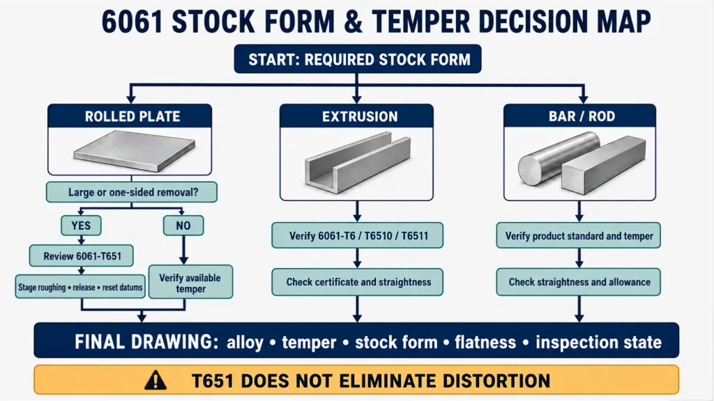
The matrix is a starting point, not a material-substitution approval. Mechanical properties, corrosion behavior, finishing compatibility, and certification requirements still need to match the drawing.
Why a T651 Part Can Still Bow, Twist, or Lose Flatness
Machining creates a new stress balance
T651 describes the condition of the supplied material. It does not describe the stress balance of the finished geometry.
A thick rectangular plate may be stable before machining because the stress field is balanced through its cross-section. Removing a deep cavity from one face creates a different cross-section. The remaining material may respond by changing curvature.
Where stock allowance and geometry permit, a light initial cut from opposing faces can expose movement before deep pocketing. The part may then be released, re-supported, and have its working datums re-established before final machining.
That does not make equal facing mandatory. A protected stock face, limited allowance, near-net geometry, or a different functional datum scheme may require another sequence.
Clamping can conceal the movement
A flexible blank can be pulled flat against a fixture, machined, and measured while restrained. It may then move after the clamps are released.
Increasing clamp force can make the setup appear more stable while increasing the difference between restrained and free-state geometry. Supports and clamps should locate the part without forcing an uncontrolled shape into compliance.
Finishing can change the final condition
Anodizing and paint may affect dimensional allowance or final inspection timing. Conversion coating and bead blasting mainly change surface condition, while racking, blasting intensity, and handling may influence very thin or flexible parts.
The drawing should state whether the applicable dimensions and geometric tolerances are inspected before or after the specified finish.
A staged sequence may be necessary
Depending on the geometry, a machining plan may include:
- Oversize roughing
- Material removal from more than one face
- Release and re-clamping
- Re-establishment of working datums
- An intermediate free-state check
- Final machining of critical faces late in the process
- Inspection after the part reaches a stable measurement temperature
These stages add setups and inspection time. They should be reviewed before quotation when final flatness or profile is a functional requirement.
Put the Procurement Condition on the Drawing
A note that says only “ALUMINUM 6061” does not control the temper, stock form, or product standard.
A complete material requirement may need to identify:
- Alloy and temper
- Plate, extrusion, bar, or another required product form
- Applicable material standard
- Certification or traceability requirements
- Whether alternative tempers or stock forms require approval
- Rolling direction or blank orientation when it is functionally controlled
- The production stage at which final tolerances apply
A project-specific drawing note could follow this structure:
Material: Aluminum alloy 6061-T651 plate to ASTM B209/B209M.
Material certification required.
Inspect the identified flatness requirement after final machining and specified finish, using the support or restraint condition defined on the drawing.
Alternative temper or stock form requires written approval before production.
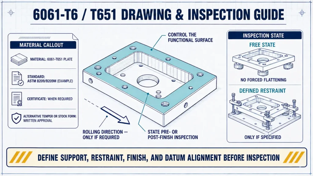
These notes do not force a project to use an ASTM standard. The governing material standard, drawing standard, title block, and purchasing requirements should remain consistent with the customer’s engineering system.
For long rails or directionally loaded components, identify rolling direction only when it affects material properties, function, nesting approval, or an established distortion-control plan. The specified orientation should then remain traceable through blank cutting and machining.
Cutter travel parallel or perpendicular to the rolling direction should not be treated as a universal anti-warp rule. Toolpath direction, workholding, removal sequence, and blank orientation are separate process decisions.
Inspect the Free Part, Not Only the Clamped Setup
Part size, form, and location are different measurement questions.
A pocket depth may pass while the surrounding face fails flatness. Hole position may appear acceptable under fixture restraint while the released part no longer aligns with the functional datum system.
| Characteristic | Suitable inspection approach | State that must be defined | Common measurement risk |
|---|---|---|---|
| Broad-face flatness | Surface plate and indicator, CMM, or another suitable form-measurement method | Free state or specifically defined restraint | Clamps or excessive probe force can suppress natural movement |
| Parallelism between faces | CMM, comparative indicator method, or calibrated dimensional setup | Part released and supported as specified | Measuring only local thickness does not establish parallelism |
| Long-rail profile or straightness | CMM, optical method, or suitable long-range measurement system | Support locations and gravity orientation | Different support points can change the measured shape |
| Pocket depth | CMM, depth gauge, or height measurement from the controlled reference | Working reference established after release when required | A distorted reference face can change the reported depth |
| Hole position | CMM or functional gauging using the drawing datum system | Functional datum alignment rather than an unconstrained mathematical fit | Alignment choices can hide datum-related error |
| Thin-wall thickness | Micrometer, CMM, or suitable ultrasonic method depending on access | Measurement force and access direction | Contact pressure may deflect the wall |
| Movement after unclamping | Repeated measurements after release and temperature stabilization | Defined time, support, and temperature when required | Immediate restrained measurement may not represent the delivered condition |
The drawing should define any permitted restraint, support method, or inspection state that materially affects acceptance. “Measure flatness” is incomplete when the part is flexible enough for gravity, support spacing, or contact pressure to change the result.
For a broader explanation of dimensional and geometric requirements, see the CNC machining tolerances guide.
Where the Quotation Cost Actually Changes
The price difference is not simply the cost per kilogram of T6 versus T651 material.
Cost may increase because of the complete stock and machining route:
- Material availability: An uncommon combination of temper, thickness, and product form may require additional sourcing or a larger minimum purchase.
- Blank allowance: More material may be needed when the machining plan requires recovery stock after roughing.
- Staged machining: Releasing, re-clamping, probing, and re-establishing datums add setup and machine time.
- Flexible geometry: Thin panels and long rails may need dedicated support or low-force workholding.
- Free-state inspection: Defined supports, stabilization, repeated measurement, or additional CMM work may be required.
- Finishing sequence: Masking, coating allowance, racking, and post-finish inspection can change the process route.
- Controlled rolling direction: Required blank orientation may reduce nesting efficiency and increase traceability work.
- Documentation: Material certification and controlled substitution requirements affect purchasing and receiving inspection.
A higher quotation does not mean that T651 is inherently difficult to machine. The cost often comes from the geometry, material-removal pattern, recovery allowance, and inspection state associated with the finished part.
For a broader comparison of aluminum materials used for dimensional control, see best aluminum for precision machining.
Review the Stock Condition Before Quotation
A useful RFQ for a 6061 plate or extrusion part should identify:
- Required alloy and temper
- Required stock form
- Applicable material standard
- Finished part envelope
- Starting thickness when it is design-controlled
- Deep pockets and the faces from which material is removed
- Minimum wall and floor thicknesses
- Flatness, parallelism, straightness, and profile requirements
- Free-state or restrained inspection condition
- Final surface treatment
- Material certification requirements
- Rolling direction when it is functionally controlled
- Permitted material or temper substitutions
Rapid Efficient can review the specified 6061 temper, actual stock form, material-removal pattern, finishing sequence, and free-state inspection requirements before quotation.
For suitable projects, submit the drawing through the CNC aluminum machining services page. Include the required stock form, major material-removal areas, final inspection state, and any permitted alternative condition so the manufacturing route can be reviewed before pricing.