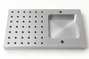
An aluminum fixture plate can arrive flat, move after pocket machining, or bend when a clamp is tightened. These problems require different checks.
MIC-6 is worth considering when a broad, accurately machined working face and low machining movement are priorities. 6061-T651 deserves closer consideration when the plate includes highly loaded features or must meet a specified structural material requirement. Either choice still needs enough remaining thickness and suitable support.
The useful comparison is between the actual plate products, the finished geometry, and the conditions in which the plate must work.
Compare MIC-6 with a Defined 6061 Product
MIC-6 is a branded, precision-machined cast aluminum plate supplied after thermal stress relief. Its product identity matters when approving a substitute.
For this comparison, 6061 means 6061-T651 rolled plate. T651 includes solution heat treatment, stress relief by controlled stretching, and artificial aging. A quotation for an unspecified 6061 blank may refer to a different product or condition.
State the required plate product, alloy and temper where applicable, material documentation, and permitted substitutions. Our 6061-T6 vs 6061-T651 guide explains how the temper designation relates to stock form and machining risk.
Separate Flatness, Machining Stability, and Stiffness
Four different properties influence a fixture plate:
- Stock flatness: the shape of the supplied surface under the supplier’s measurement conditions.
- Machining stability: how much the part changes shape as material is removed and restraints are released.
- Elastic stiffness: resistance to recoverable deflection under load.
- Yield strength: the stress level associated with the onset of permanent deformation under a defined test criterion.
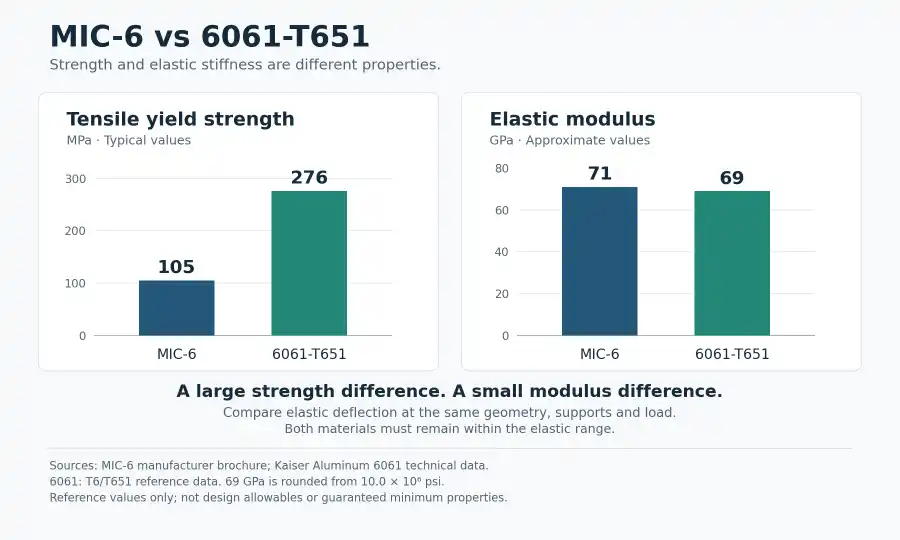
The MIC-6 manufacturer brochure and Kaiser 6061 technical data illustrate why strength and stiffness must be separated.
| Typical reference property | MIC-6 | 6061-T6/T651 reference data |
|---|---|---|
| Tensile yield strength | 105 MPa | 276 MPa |
| Approximate elastic modulus | 71 GPa | 69 GPa |
Elastic modulus values are approximate. The 6061 value is rounded from the source’s 10.0 × 10⁶ psi figure. These figures come from separate manufacturer publications. They are reference values, not minimum purchase requirements or design allowables. Verify the applicable product specification, thickness, material direction, and required properties.
The yield-strength difference is substantial, while the elastic moduli are close. For the same geometry, supports, and load within the elastic range, changing between these materials produces only a small stiffness change. Neither modulus value predicts residual-stress movement during machining.
Also compare specific supplier products. KaiserSelect general engineering plate, for example, includes 6061-T651 options intended to improve residual-stress and flatness control.
Compare the supplier’s specified plate product before judging machining stability from cast or rolled labels alone.
A Deep Pocket Can Matter More Than the Alloy Change
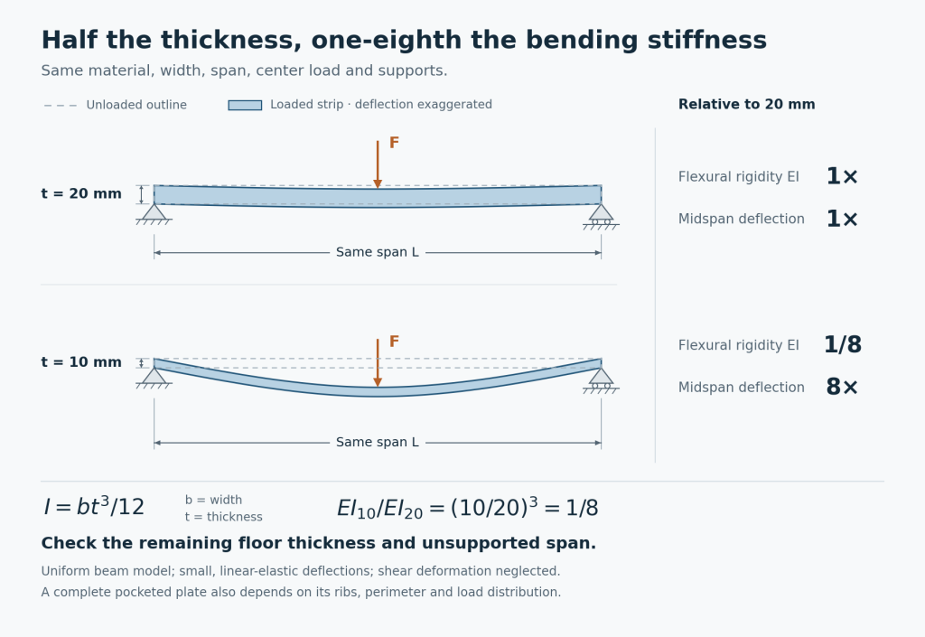
Consider two uniform rectangular strips with the same width, material, span, loading, and support conditions. One is 20 mm thick; the other is 10 mm thick.
For bending about the centroidal axis parallel to the width, the second moment of area is:
I = b × t³ / 12
Here, b is the strip width and t is its thickness. I describes the cross-section geometry. The beam’s flexural rigidity is E × I, which also includes the material’s elastic modulus. This distinction is set out in MIT’s beam theory notes.
The thickness change gives:
I(10 mm) / I(20 mm) = (10 / 20)³ = 1/8
Under these assumptions, and neglecting shear deformation, the thinner strip has one-eighth of the flexural rigidity and eight times the deflection in a small-deflection, linear-elastic beam model.
A complete pocketed plate may behave differently because its perimeter, ribs, supports, and load distribution also matter. The calculation demonstrates the thickness effect; it is not a prediction for every fixture plate.
Shortening the unsupported span, adding support beneath a clamp, or leaving a thicker floor may address the problem more directly than changing the material.
Check the remaining section and unsupported span before trying to solve the problem with a material substitution.
Choose Around the Working Face and the Load Path
Start with the surface that must stay accurate and follow the force through the plate to its supports.
| Plate feature or working condition | Material consideration | Design or process check |
|---|---|---|
| Broad working face with shallow machining | Consider MIC-6 when the supplied face and plate properties suit the job | Confirm whether the stock face can remain and whether the finished flatness requirement is met |
| Narrow mounting ears, thin bolt lands, or concentrated loads | Review the higher yield strength of 6061-T651 | Check local stress, bearing area, edge distance, and the remaining section |
| Wide pocket with a thin floor | Either material can remain too flexible | Review floor thickness, support spacing, clamp locations, and cutting forces |
| Flatness checked while the plate is bolted down | Either material can appear acceptable under restraint | Define whether acceptance applies in the free state or under specified mounting conditions |
For locating pins that are repeatedly removed or carry significant side loads, consider replaceable hardened locating bushings. Review their installation fit, surrounding wall thickness, and the final pin fit and location after installation.
For a vacuum fixture, specify the operating vacuum level, allowable leakage, and test method. Verify the finished assembly after machining the channels and installing plugs and seals. State whether the test uses continuous pumping or an isolated volume. Material identity alone does not establish the assembly’s leak performance.
Review Threaded Holes as Loaded Features
A clamp screw can place a substantial load into a small volume of aluminum. Review bolt preload, service loading, usable thread engagement, edge distance, and the material remaining between the hole and nearby pockets.
A tensile yield value cannot be used directly as a thread-stripping capacity. The joint also depends on thread geometry, fastener strength, engagement, and how the load enters the surrounding plate.
For repeated fastener changes or demanding joints, consider suitable threaded inserts. Their installation must leave enough parent material to carry the load. An insert can improve the working thread, but the surrounding boss and plate still require review.
Select thread engagement for the joint. A fixed engagement multiple or an instruction to install inserts in every hole does not replace that assessment.
Specify the Anodized Appearance Separately
Both materials can be anodized. The MIC-6 manufacturer describes a naturally darker gray appearance and possible shade or texture variation. Choosing 6061 also does not establish a guaranteed color match.
For a visible fixture face or a plate that must match adjacent components, specify the anodizing process, color, texture, and cosmetic acceptance reference. When appearance is critical, review a representative sample using the proposed material and finishing route.
Functional coating requirements need separate attention. Identify critical bores, locating features, threaded holes, and any masking areas so coating buildup is included in the dimensional plan.
Our surface finishes guide explains the broader finishing options. For this plate comparison, confirm both the required coating function and the acceptable appearance before production.
Define Acceptance for the Finished Plate
A stock flatness tolerance applies to a stated product and measurement condition. The finished fixture needs its own acceptance requirements.
The drawing and inspection plan should identify:
- The working faces and their separate flatness and parallelism requirements.
- The datum system for locating holes, pockets, and mounting features.
- Whether inspection occurs after final machining, after finishing, or at both stages for different characteristics.
- The support locations, gravity orientation, and any permitted restraint during measurement.
- The finished condition of coated, masked, or insert-equipped features.
A plate pulled flat against a fixture may pass a restrained check and move after release. If free-state geometry is required, the inspection setup must not force the surface into compliance. If mounted geometry is required, define the mounting conditions.
For flexible plates, measurement force and temperature stabilization may also affect the result. Our CNC machining tolerance guide explains how dimensional and geometric requirements fit into the inspection plan.
Compare Quotes for the Same Finished Base
Compare the cost of meeting the same finished-part requirements. Stock price alone does not capture face preparation, staged roughing and finishing, release checks, insert installation, finishing trials, or final inspection.
If a supplied MIC-6 face meets the finished requirement, preserving it may avoid a facing operation. If that face must be removed or the final geometry requires further correction, the machining plan changes. A suitable 6061-T651 product may also reduce process risk when its properties and supplied condition match the design.
Identify any additional thermal treatment explicitly. Do not assume that either purchased plate needs a routine post-machining heat-treatment cycle.
For a fixture or base plate, send the drawing with the remaining pocket-floor thickness, unsupported spans, clamp and load locations, frequently used holes, final flatness requirements, and finishing requirements.
Through our CNC aluminum machining services, RapidEfficient can review stock options, machining sequence, finishing, and inspection requirements before quotation. Mark unresolved requirements so the proposed route and quotation can state their assumptions clearly.