Titanium CNC machining requires control of heat at the cutting edge while maintaining a chip thick enough for the tool to cut effectively. Turning down the feed alone can make an already thin chip smaller, increasing rubbing instead of solving the problem.
The finished geometry creates another constraint. A strong titanium bracket can still have a flexible wall, and a dimension measured while that wall is clamped may change after release.
This guide focuses on carbide milling of titanium pockets and thin walls. A practical machining plan connects the titanium grade and condition with cutter engagement, coolant access, tool condition, and the support remaining around each feature. Those decisions should be made together before assigning cutting parameters or promising a finished tolerance.
Identify the Titanium Grade Before Reusing Cutting Data
“Titanium” is not a complete material specification.
Grade 2 is commercially pure titanium. Grade 5, Ti-6Al-4V, is an alloy with different strength and machining behavior. The supplied condition also matters. For Ti-6Al-4V, cutting data should be reviewed when moving between conditions such as annealed and solution treated and aged.
TIMET’s titanium datasheets distinguish commercially pure grades from the different alloy families. A drawing and purchase order should identify the required grade, governing material specification, stock form, and supplied condition.
For a repeat job, a change from plate to bar, a different heat-treatment condition, or a change in stock preparation deserves review even when the finished CAD model is unchanged.
If the material choice is still open, our 7075 aluminum vs Grade 5 titanium comparison addresses that earlier decision. Once titanium is required, the machining route must be built around the specified material rather than an aluminum program with a lower spindle speed.
A Smaller Feed Does Not Always Produce a Better Cut
Titanium’s low thermal conductivity limits how quickly heat moves away from the cutting region. Its interaction with the cutting edge can also contribute to material pickup, smearing, and tool wear.
TIMET’s machining guidance emphasizes controlled cutting speed, effective feeding, sharp tools, coolant, and rigid setups. These factors work together. Reducing feed while leaving an unsuitable cutting speed, worn edge, or poor coolant delivery unchanged may not address the cause.
For milling, distinguish three quantities:
- Cutting speed: the speed of the cutting edge relative to the workpiece.
- Feed per tooth: the programmed advance associated with each cutting tooth.
- Chip thickness: the material thickness actually presented to the edge during engagement.
Feed per tooth and maximum chip thickness are not always equal.
Radial Engagement Changes the Chip Thickness
In peripheral milling, a smaller radial width of cut produces chip thinning when engagement is below half the cutter diameter. Sandvik Coromant’s chip-thickness guidance explains this relationship and the need to match feed to engagement.
Consider an illustrative straight side-milling operation with:
- Cutter diameter, D = 10 mm.
- Feed per tooth, fz = 0.050 mm/tooth.
- A cylindrical cutter cutting on its peripheral edges.
- Negligible runout and deflection.
For radial engagement from greater than zero up to 50% of the diameter, a common idealized approximation is:
Maximum chip thickness ≈ fz × 2 × √[x × (1 − x)]
where x = radial width of cut ÷ cutter diameter.
| Radial width of cut | Engagement relative to diameter | Programmed feed per tooth | Approximate maximum chip thickness |
|---|---|---|---|
| 5.0 mm | 50% | 0.050 mm/tooth | 0.050 mm |
| 1.0 mm | 10% | 0.050 mm/tooth | 0.030 mm |
| 0.5 mm | 5% | 0.050 mm/tooth | 0.022 mm |
At 5% engagement, the maximum chip is less than half the programmed feed per tooth. Reducing feed again would make it thinner still.
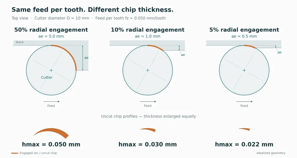
These values demonstrate geometry; they are not recommended titanium cutting parameters. A 0.022 mm chip is not automatically too thin. Suitability depends on the tool diameter, edge preparation, material condition, operation, and toolmaker’s recommended range.
The approximation also does not describe every milling operation. Ball-end cutting, round inserts, changing corner engagement, and other tool geometries require the appropriate calculation.
Use the toolmaker’s data to select an effective chip thickness, then check the feed against machine capability, tool strength, surface requirements, and workpiece stiffness.
Cutting direction also affects how the edge enters the material. In peripheral climb milling, the chip starts thicker and becomes thinner toward exit, reducing the initial rubbing associated with conventional milling. Sandvik’s guidance on milling direction favors climb milling where the machine, fixture, and workpiece allow it. Backlash control, workholding, and cutting-force direction still need review, particularly around flexible walls.
Check the Corners and the Coolant Path Together
A cutter may run smoothly along a straight wall and struggle as it enters an internal corner.
The radial arc of engagement can increase there, placing more of the cutter in contact with the workpiece. A feed selected for light side cutting may then produce a substantially different load. Sandvik’s guidance on milling inside corners identifies this engagement change as a source of instability and edge damage.
Review the actual remaining stock and toolpath, including entry moves, corners, and cleanup passes. Options include smoother entry, controlled-engagement paths, a smaller cutter for corner cleanup, or a larger permitted internal radius.
A toolpath change must still leave the finished corner within the drawing requirement.
Coolant access deserves the same local review. A nozzle that reaches an open wall may be blocked when the cutter moves deeper into a pocket. Chips may also collect where they cannot leave the cutting zone easily.
For carbide titanium milling, Sandvik’s material-specific guidance recommends coolant to help control edge temperature and remove chips. Through-tool delivery can be useful where external access is limited.
Pressure alone does not describe the complete system. Flow, nozzle direction, filtration, tool passages, fluid compatibility, and chip exit space also matter. Use the tool and coolant suppliers’ requirements for the actual operation.
When vibration remains a problem, use the machining chatter guide to separate setup movement, engagement changes, and vibration behavior before changing several parameters at once.
Preserve Support as Titanium Walls Become Thinner
High strength does not prevent elastic deflection. Titanium has a lower elastic modulus than steel, so an otherwise comparable titanium section can deflect more under the same load.
In a pocketed part, the setup also changes during machining. Material that supported a rib early in roughing may be gone by the finishing pass.
Sandvik’s thin-wall milling guidance describes strategies that retain support, alternate machining on opposing sides, and approach the finished wall in stages. The appropriate sequence depends on wall height, thickness, accessibility, and the stability of both tool and part.
Consider an illustrative titanium bracket with a tall rib between two pockets. Finishing one pocket completely before roughing the other can leave the rib thin while substantial cutting remains nearby.
A process planner should evaluate whether roughing both pockets with material left around the rib, followed by staged finishing, provides better support. Temporary stock or a removable support feature may also be useful where the geometry allows it.
The support needed during cutting may be material that does not exist in the finished part.
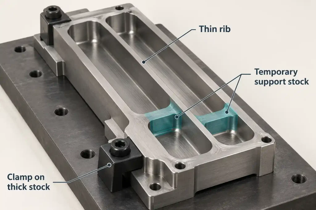
That support must have a planned removal operation. Its removal can change the part’s shape or expose an edge that needs finishing, so final inspection should follow the relevant release and cleanup steps.
Clamping needs similar care. Extra force can suppress movement during machining while bending the part into the fixture. If the drawing requires a free-state dimension, inspection must not hold the part flat merely to obtain an acceptable reading. Where a restrained condition is specified, reproduce that condition deliberately.
Use Tool Wear to Define When the Process Needs Attention
A tool can continue cutting after its condition has become unsuitable for a critical surface.
For carbide titanium milling, select the substrate, coating, cutting geometry, and edge preparation together using the toolmaker’s application data. A coating name or a single clearance angle is not enough to select a cutter for every titanium grade and operation.
Notch wear, flank wear, edge chipping, and adhered material are relevant inspection points. The useful replacement limit depends on the tool and the feature being produced; a single wear limit should not be applied to every cutter and operation.
For production planning, connect tool checks to observable part changes:
| Observation | Evidence to collect before changing the program |
|---|---|
| Finish deteriorates mainly near corners | Local remaining stock, engagement changes, edge damage, and coolant access |
| Rib thickness or straightness changes after unclamping | In-fixture and released measurements, support locations, and clamp sequence |
| Burrs grow while the main dimensions remain acceptable | Cutting-edge condition, exit geometry, and the deburring operation |
| Successive parts show dimensional drift | Measurement trend, tool condition, offsets, and part temperature |
These observations guide an investigation; none proves a cause by itself.
For a repeat titanium order, the supplier should know which feature controls tool replacement and what evidence is checked after a tool change. A low cycle time achieved only with a fresh cutter may not represent the cost or consistency of the whole batch.
Define the Delivered Surface and Measurement Condition
A titanium part can meet its main dimensions while still requiring additional work at a thread entry, cross-hole intersection, sealing edge, or thin rib.
Identify edges where a loose burr is unacceptable and surfaces where an unrestricted edge break would remove functional material. “Deburr all edges” may be insufficient for a sharp sealing boundary or a small locating feature.
Specify the required cleaning and final surface condition as well. Machining fluid, polishing residue, and loose debris should be addressed through the agreed cleaning process. If welding, bonding, coating, or another operation follows machining, its preparation requirements belong in the manufacturing plan.
For critical features, establish what the inspection result must represent:
- The correct drawing datum.
- The specified free or restrained condition.
- The completed deburring and finishing stage.
- An appropriate measurement temperature and method.
- The required surface texture and accessible measurement location.
A roughness result describes the measured texture. It does not independently prove that the entire surface is free from local damage or that the part meets a fatigue requirement. Additional acceptance requirements must be specified where the application needs them.
Our CNC machining tolerance guide explains how feature geometry, measurement conditions, and finishing affect the tolerance budget.
Put the Difficult Titanium Features Into the Quotation Review
The machining cost depends on more than stock price. Deep pockets can restrict coolant access and require longer tools. Thin ribs can require staged cutting and extra setups. Inaccessible edges can add deburring and inspection work.
When comparing quotations, show the supplier which of those features must remain unchanged and where design adjustments are possible. That makes it easier to distinguish necessary processing from avoidable cost.
For a titanium component, provide the exact grade and supplied condition, mark the thin walls and deep pockets, and identify critical edges, finished dimensions, and any later welding or surface treatment. If a trial part already exists, include where dimensions change after release or where tool wear first affects the surface.
Through our CNC machining services, RapidEfficient can review those features and coordinate the proposed machining, support, cleaning, and inspection requirements before quotation.