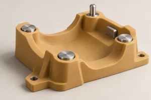
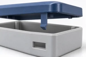
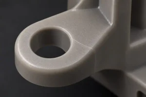
Two metal-printing quotes can use different process names and still describe the same broad manufacturing method. They can also use the same name while offering different material properties, surface conditions, and inspection scope.
In current metal additive manufacturing, DMLS and SLM generally refer to implementations of laser powder bed fusion (LPBF). Neither name alone tells you which supplier will deliver the better finished part. Compare the specified alloy, machine and process settings, build orientation, post-processing, and acceptance requirements.
The useful question is what changes between the two proposed manufacturing routes.
DMLS and SLM Belong to the Same Process Family
DMLS is widely expanded as direct metal laser sintering. SLM means selective laser melting. That wording can suggest that DMLS only joins particles below their melting temperature while SLM melts them completely.
This is not a reliable distinction for current commercial equipment. EOS describes its DMLS technology as laser powder bed fusion in which the laser melts the selected areas of metal powder.
In this process family, a thin powder layer is spread across the build area. The laser selectively melts the required regions, which solidify and join the preceding material. Repeating the operation builds the part.
The names also do not create an “alloys versus pure metals” split. Material availability depends on the machine and its supported material processes. Compare the exact alloy offered rather than inferring compatibility from the process name.
This does not make every DMLS and SLM machine interchangeable. Available materials, process parameters, monitoring, build volume, and demonstrated results can differ. Ask which system and material process the quotation actually covers.
Read the Conditions Behind the Material Properties
A strength value is only useful when its test conditions match the comparison.
Check the exact alloy designation, material condition, specimen orientation, and test method. Also distinguish a typical result from a specified minimum or a statistically defined lower bound.
A useful material report identifies the machine and process used to produce the specimens and separates results by build orientation and material condition where relevant. Those results should not be assumed to transfer unchanged to a different system.
That is a more useful comparison basis than a generic “DMLS strength” or “SLM strength” number.
If one quotation refers to as-manufactured specimens and another to heat-treated specimens, the difference cannot be assigned to the process name. Likewise, data from machined test specimens do not automatically describe the performance of a part with rough, inaccessible surfaces.
Agree on the required final material condition before comparing results. Do not assume that every printed alloy needs the same heat-treatment cycle, or that one supplier’s validated settings can be moved unchanged to another machine.
Powder history also belongs in this review. For reused powder, ask how the supplier records powder batches, reuse and mixing, and checks continued suitability. Chemistry limits and reuse controls should follow the applicable alloy requirements and validated process rather than a universal reuse count or blend ratio.
If the proposed alloy itself is uncertain, our guide to metal 3D printing material limitations addresses that separate selection question.
Follow One Manifold from Powder to Finished Interfaces
Consider an illustrative metal manifold with a curved internal passage, threaded connection ports, and a flat mounting face. Both suppliers offer the specified alloy, but one labels the process DMLS and the other SLM.
Start by reviewing their proposed build plans.
The curved passage needs a practical powder-removal route. An opening in the CAD model does not, by itself, demonstrate that powder can be cleared through every bend and narrow section. If the passage requires internal supports, their removal must also be feasible.
For a channel roof that is difficult to build without support, review the build direction and whether a teardrop or diamond section could meet the flow requirement. Confirm the choice against the selected machine, alloy, and process. A general overhang rule or nominal diameter alone cannot establish whether the passage will print, clear, and function as intended.
A printed channel is only useful if it can be cleared and its working condition can be verified.
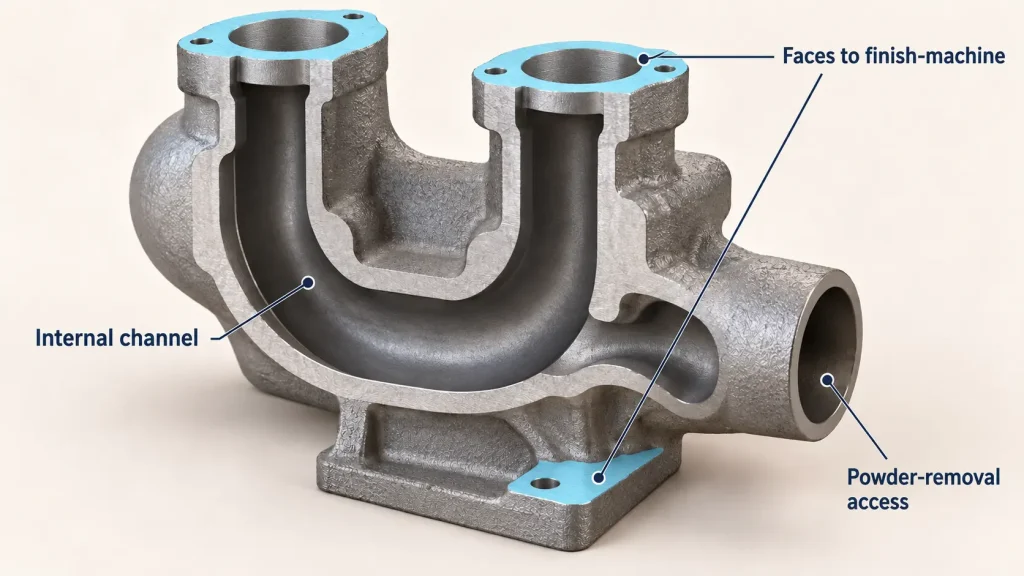
Changing the build orientation may alter the surfaces that face downward, the support locations, and the effort needed after printing. These are build-plan decisions, not fixed differences between the two process names.
Before printing, agree on the sequence for depowdering, heat treatment, separation from the build plate, support removal, and finish machining. Define how loose powder will be removed from the internal passage and how completion will be checked before heat treatment. Removing restraint can allow residual stress to change the part’s shape. If the validated route requires stress relief while the part remains on the plate, complete that step before separation. Specify the treatment cycle and furnace atmosphere for the alloy and process.
Now follow the external interfaces. If the ports require finish machining or the mounting face needs a controlled flatness and surface finish, identify those operations before printing. Review machining stock, tool access, and the surfaces used to locate and hold the part.
Machining allowance must be assessed for the actual geometry and expected variation. A single stock value applied everywhere may leave too little material in one region or unnecessary removal elsewhere.
The CNC machining tolerance guide can support the drawing discussion for these finished interfaces. Keep their acceptance requirements separate from the condition permitted on surfaces left as printed.
The meaningful comparison is whether each proposed route can deliver the same usable passage and finished interfaces.
A Density Figure Does Not Prove Fatigue Life or Leak Tightness
High relative density can be useful evidence, but it does not describe every defect or establish every functional requirement.
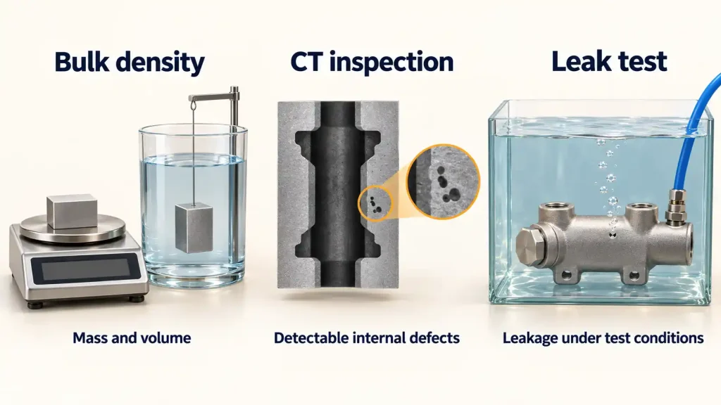
A bulk density result does not tell you where the remaining defects are, how large they are, or whether they form a connected leakage path. Defect location also matters when evaluating fatigue-sensitive parts.
For the manifold, separate three questions:
- Does the material meet the agreed material-property requirements?
- Are the internal passage and relevant defects acceptable under the specified inspection method?
- Does the finished component meet its leakage requirement under defined test conditions?
These questions require different evidence. A density report cannot replace a leak test when leak tightness is required. An internal scan must have suitable detection capability and acceptance criteria; a scan image alone is not a universal pass certificate.
If hot isostatic pressing is proposed, treat it as a specified post-processing operation with its own purpose and validation needs. Do not assume it makes every defect harmless or replaces the required functional testing.
Use the first article inspection guide to organize the agreed evidence. The report should identify which characteristics were checked and which require separate tests.
Put Both Quotes at the Same Delivery Stage
A price for a printed blank cannot be compared directly with a price for a heat-treated, machined, cleaned, and inspected component.
For the manifold example, resolve the following differences before deciding whether a DMLS or SLM quotation offers better value.
| Quotation statement | What remains unclear | What makes the comparison meaningful |
|---|---|---|
| “DMLS” or “SLM” | The actual equipment and supported material process | Identify the machine, alloy, and applicable process specification |
| “High-strength metal” | Material condition, test direction, and acceptance basis | Compare data under relevant, stated conditions |
| “Internal channel included” | Powder clearance, support removal, and internal acceptance | Review the passage and its cleaning and inspection route |
| “Finished ports” | Whether threads, sealing faces, and their inspection are included | Mark the interfaces and define their delivered condition |
| “High density” | Whether leakage or fatigue requirements have been addressed | Specify the evidence required for the part’s actual function |
| “Ready to ship” | Which post-processing and verification steps are included | Compare the same completed scope and quantity |
Build time is only part of that scope. Support removal, heat treatment where required, machining, cleaning, and inspection can change both price and delivery. A shorter print cycle does not necessarily produce an earlier accepted part.
Once the alloy, final condition, geometry, and acceptance requirements are aligned, differences between the quotations become easier to evaluate. The process acronym remains useful for identifying the route, but it is not a substitute for that review.
For a metal part with internal passages or machined interfaces, send the CAD model and drawing with those features identified, together with the required material condition and any cleanliness, leakage, or load requirements. Through our metal 3D printing services, Rapid Efficient can review the proposed build and finishing route and coordinate project-specific manufacturing and inspection requirements before quotation.