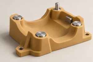
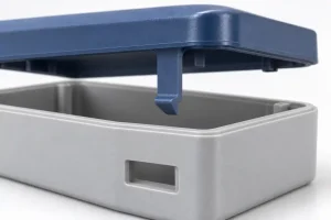
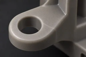
A plastic housing may need a soft grip, metal mounting threads, or both. These features introduce different requirements: the grip must stay attached at its edges, while the threaded insert must remain in position and resist assembly loads.
Overmolding adds molded material over an existing substrate. Insert molding places a preformed component in the mold and molds material around it. The terms can overlap: a separately molded plastic substrate can be loaded as an insert and then overmolded.
To compare the processes for a particular part, identify what enters the mold, what keeps the materials together, and how the finished joint will be loaded.
Separate the Added Material from the Loading Sequence
Overmolding describes the relationship between a substrate and an added layer. Insert molding emphasizes the preformed component placed inside the tool. Neither term, by itself, fully defines the production sequence.
| Part requirement | What is present before the molding step? | What the next shot creates |
|---|---|---|
| Soft grip on a rigid housing | A rigid plastic substrate | A soft layer over selected surfaces |
| Threaded metal attachment point | A preformed threaded insert | A plastic body around the insert’s retention features |
| Two-material plastic part made in an integrated cycle | The first molded material | A second material molded against the first |
A soft grip can be made by transferring a separately produced substrate into another mold. It can also be made through a two-shot process that produces the first shot and presents it to a second molding station within an integrated system.
Specifying “overmolding” therefore does not automatically specify two-shot tooling.
For quotation, identify whether the substrate or insert will arrive as a finished component or must be manufactured as part of the proposed process.
Decide What Keeps the Materials Together
For a soft layer over rigid plastic, start with the exact material pair. “TPE over nylon” is not a complete adhesion specification.
Select an overmolding formulation for the exact substrate grade. A formulation intended for one plastic should not be assumed to bond equally well to another. Confirm the proposed grades with the material supplier and evaluate the actual molded combination.
Substrate handling also matters. Protect stored parts from contamination and follow the material supplier’s drying and processing instructions. Preheating may help some combinations, but it is not a universal requirement. Avient’s TPE overmolding guide identifies nylon applications in which preheating can reduce adhesion. Set substrate temperature and transfer conditions for the selected materials, then validate them through molding trials.
Mechanical capture can provide another retention mechanism. Material passing through a hole or wrapping behind a feature can resist separation even where adhesion is limited. However, a mechanically retained layer can still lift locally between its retention points.
The design review should distinguish the following functions:
| Interface | Load or exposure to define | Design question | Acceptance evidence |
|---|---|---|---|
| Soft grip edge | Peeling caused by handling or repeated use | Can an exposed edge initiate separation? | Peel or repeated-use evaluation on representative parts |
| Threaded insert | Axial loading and assembly torque | What prevents extraction and rotation? | Separate pull-out and rotational resistance tests |
| Metal terminal in a plastic body | Mating force and permitted movement | What holds its position during molding and use? | Position measurement and a defined retention test |
| Overmolded sealing boundary | Specified fluid, pressure, and temperature | Is the sealing path continuous under service conditions? | Leakage testing under defined conditions |
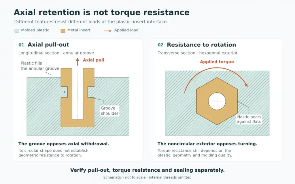
A circumferential retention groove illustrates why load direction matters. Plastic filling the groove can oppose axial withdrawal. Because the groove is rotationally symmetric, it does not create the same geometric resistance to turning as a suitable noncircular feature. Friction and other features may contribute, but axial retention alone does not establish torque resistance.
Similarly, mechanical capture does not establish a leak-tight interface. A part may remain securely assembled while fluid passes along the material boundary.
Retention geometry also needs a manufacturing review. If a feature must first be formed in the plastic substrate, check its release path using the undercut release guide. A useful retention feature can still complicate the substrate’s mold.
Give the Insert a Seat Before the Melt Arrives
The insert’s final position depends partly on how the tool holds it during filling.
The insert or substrate needs support against molding pressure. Areas occupied by tool contacts cannot receive overmold material during that molding step. Shutoffs—the contacts that stop plastic flowing beyond the intended boundary—also need deliberate placement.
On the drawing or CAD model, distinguish three regions:
- Surfaces that locate and support the insert.
- Surfaces that receive molded material.
- Surfaces that must remain exposed and free of flash.
For a threaded insert, review how it is seated, which features establish its axis and height, and how resin is prevented from entering the threaded opening. A locating fit and a resin shutoff serve different purposes; the design must address both.
The appropriate protection depends on the insert and tool arrangement. A blind-end insert can block resin entry through its closed end, but the accessible threaded opening still needs a suitable shutoff.
For slender inserts, review the unsupported length, stiffness, support locations, and direction of filling. Where filling loads could move or bend the insert, evaluate additional support or changes to the gate arrangement. Check the resulting flow pattern and weld-line locations before adopting additional gates.
An insert needs a defined locating and support scheme before the surrounding plastic can hold it in service.
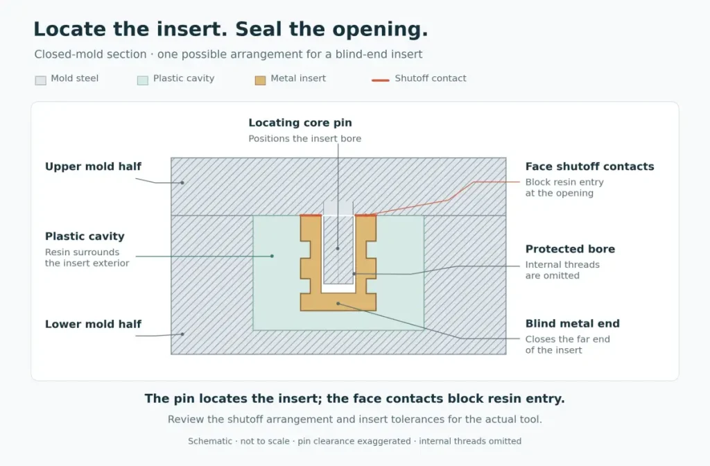
Do not assign a tight insert-position tolerance solely from the nominal CAD assembly. Review the insert’s own dimensional variation, its seating in the tool, and its measured position after molding.
The injection mold tooling review should therefore include the insert or substrate model, its tolerances, permitted tool contact areas, and the features that must remain accessible.
Compare Production Routes for the Same Interface Requirements
Once a material combination and retention concept have been identified, compare how the part will move through production.
For an overmolded grip, separately producing and transferring the substrate can separate the two molding operations. Two-shot production integrates them more closely but requires a suitable tooling and equipment arrangement. Bond results should be validated for the proposed route; changing from one route to the other can change the interface conditions.
There is no universal production quantity at which one approach becomes cheaper. Build the comparison around the proposed part and quotation:
- Tooling and equipment requirements.
- Substrate or insert production and handling.
- Loading, orientation checks, and inspection.
- Expected design changes and their tooling consequences.
- The cost of components already present when a molding operation rejects a part.
The last point is easy to miss. If an overmolding defect causes a complete assembly to be scrapped, the loss may include a finished substrate or purchased insert. Comparing molding cycle cost alone can hide that exposure.
For a threaded attachment point, also ask whether the insert needs to be molded in at all. Depending on the resin, geometry, access, and loads, a suitable post-installed insert may be another candidate. It requires its own installation and validation process and should be evaluated as a separate production option.
Compare the cost of accepted assemblies meeting the same requirements, including the required joint performance and inspection.
Test the Joint in the Direction It Will Be Loaded
A visually complete overmold is not sufficient evidence of joint performance.
For threaded inserts, evaluate resistance to rotation and axial pull-out separately. The plastic, insert geometry, molding or installation quality, and mating assembly all influence performance. Catalog results are useful comparisons, but they do not establish the strength of a different production assembly.
For a threaded insert, specify what each test is intended to establish. Resistance to the insert turning in the plastic is different from the torque applied while tightening the actual fastener. The fastening joint also needs its intended mating component and support conditions represented.
For a grip, evaluate the edges and transitions that users can pull, bend, or rub. If cleaners or elevated temperatures are part of service, include the relevant conditioning rather than approving only an unconditioned sample.
For a seal, define the test medium, pressure, temperature, duration, and allowable leakage. “Waterproof overmolding” leaves too much of the acceptance decision unstated.
For each applicable test, agree on the load level, loading direction, fixture, sample quantity, and acceptance criteria. Where repeated use matters, define the required cycles and what counts as failure, such as edge lifting, insert movement, loss of retention, or leakage.
Dimensional acceptance needs its own checks: insert position, exposed height, flash on functional surfaces, and the dimensions of the completed part. Use the first article inspection guide to organize the drawing characteristics, while keeping functional joint testing explicit.
A dimensional report and a joint-performance test answer different questions; define both when the application requires them.
Show the Material Boundary in the Drawing Package
The most useful drawing package makes the interface visible.
Provide the substrate, insert, and added material as identifiable bodies in the CAD model. Mark the surfaces to be covered, surfaces that must remain exposed, and areas where flash or tool contact is unacceptable. Include exact resin grades or clearly identify which material selections remain open.
Add the service requirements at that interface: peeling, axial loading, assembly torque, sealing, temperature exposure, or repeated use. Include the expected production quantity and whether inserts or substrates will be supplied.
Through our overmolding services, Rapid Efficient can review the proposed material combination, substrate support, and tooling requirements before quotation. Identifying the interface requirements early gives that review a concrete basis for comparing production routes and agreeing on validation.