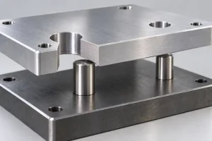
Positional tolerance in GD&T controls how far a feature may depart from its theoretically exact location. For a round hole with a diametrical position callout, the tolerance zone is cylindrical. Its location and orientation come from the drawing’s basic dimensions and datum references.
The hole diameter remains a separate requirement. A hole can have the correct size and still miss a locating pin, interfere with a fastener, or misalign with another bore. Where position is specified at maximum material condition, departure from that material condition can provide additional positional tolerance—but it does not remove the hole’s size limits.
The examples below use an ASME-style drawing framework for cylindrical holes. Confirm the drawing’s specified edition of ASME Y14.5 before applying these examples to an inspection plan. ISO GPS drawings require interpretation under their own applicable standards.
Read the Hole Size and Position Callout Together
Consider a mounting plate with a through-hole. Its drawing specifies:
| Drawing information | Illustrative requirement | What it establishes |
|---|---|---|
| Hole size | Ø10.00–10.20 mm | Permitted hole diameter |
| Basic X location | 40.00 mm | Theoretically exact X location |
| Basic Y location | 25.00 mm | Theoretically exact Y location |
| Position tolerance | Ø0.20 mm, with no material-condition modifier | A cylindrical position zone of fixed diameter |
| Datum references | A, then B, then C | The reference hierarchy used to locate and orient the zone |
Assume A is the mounting face, B is a perpendicular side face, and C is a perpendicular end face. Together, these establish the reference frame for this example.
The basic dimensions locate the true position. They are not ordinary dimensions with an additional ± allowance. The position callout supplies the permitted geometric variation.
Under the ASME framework used here, no material-condition modifier on the position tolerance means regardless of feature size, or RFS. Increasing the hole diameter within its size limits does not increase the Ø0.20 mm position tolerance.
The cylindrical zone also limits the hole axis’s orientation over the controlled length. A separate, tighter orientation requirement may be useful where function needs it, but position is not merely a check of the center point at the hole entrance. The distinction between orientation and location is explained further in the perpendicularity GD&T guide.
Why Two Small Coordinate Errors Can Fail Position
For a perfectly cylindrical hole whose axis is parallel to its nominal direction, the diametrical position deviation can be calculated from the transverse coordinate errors:
Position deviation = 2 × √(ΔX² + ΔY²)
Here, ΔX and ΔY are the differences between the measured and basic coordinates in the specified datum reference frame.
Suppose the hole center is measured at:
- X = 40.08 mm instead of 40.00 mm.
- Y = 25.08 mm instead of 25.00 mm.
The calculation becomes:
2 × √(0.08² + 0.08²) ≈ 0.226 mm
That exceeds the Ø0.20 mm position tolerance.
Both coordinate errors are smaller than 0.10 mm, but the combined radial offset is approximately 0.113 mm. The permitted radius of the position zone is only 0.100 mm.
A Ø0.20 mm position zone is not equivalent to independent ±0.10 mm limits in X and Y.
Independent coordinate limits create a square acceptance region in this cross-section. The diametrical position requirement creates a circle. Points near the square’s corners lie outside that circle.
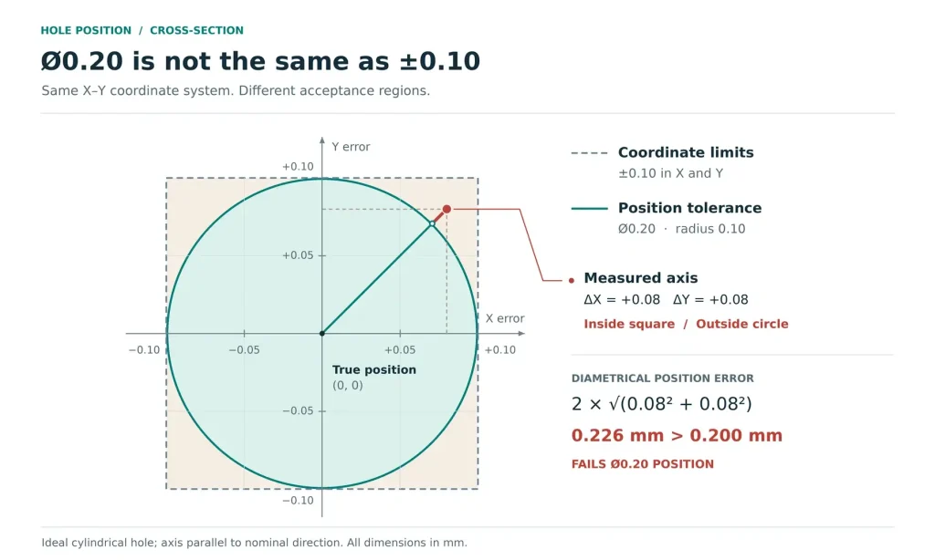
The factor of two converts radial offset into the diameter of the centered zone needed to contain the displaced axis. It does not mean the hole itself has doubled in size.
This calculation describes the stated parallel-axis example. If the hole axis tilts, a single center measurement cannot establish its position over the full controlled length.
MMC Changes the Available Tolerance, Not the Basic Location
Now change the example’s position requirement to Ø0.20 mm at MMC, while keeping the hole size at Ø10.00–10.20 mm.
For an internal feature such as a hole, MMC is the smallest permitted diameter: 10.00 mm. This leaves the greatest amount of material in the part.
For the ideal cylindrical holes used in this example:
Bonus tolerance = actual hole diameter − MMC hole diameter
Total position tolerance = stated position tolerance + bonus tolerance
A hole measuring 10.12 mm therefore has:
- Bonus tolerance: 10.12 − 10.00 = 0.12 mm.
- Total position tolerance: 0.20 + 0.12 = Ø0.32 mm.
The basic X and Y locations remain unchanged. The permissible zone grows around the same true position.
| Ideal hole diameter | ΔX | ΔY | Calculated position deviation | Total available position tolerance | Position result |
|---|---|---|---|---|---|
| 10.00 mm | 0.08 mm | 0.08 mm | 0.226 mm | 0.200 mm | Fail |
| 10.12 mm | 0.12 mm | 0.09 mm | 0.300 mm | 0.320 mm | Pass |
| 10.12 mm | 0.12 mm | 0.12 mm | 0.339 mm | 0.320 mm | Fail |
These are teaching examples, not measured production results. They assume straight, round cylinders without tilt or form error, evaluated in the same fixed datum reference frame. Displayed results are rounded; acceptance calculations should retain sufficient precision.
For a real hole with taper, lobing, or other form error, an arbitrary diameter reading is not a reliable basis for bonus tolerance. Under the ASME framework used here, the relevant size is the unrelated actual mating envelope (UAME). For a hole, this is the largest perfect cylinder that can fit within the hole over the applicable feature length, without being constrained to the datum reference frame. The inspection method must estimate this envelope appropriately and verify the hole’s size limits separately.
Bonus does not excuse an oversized or undersized hole. A 10.25 mm hole would violate this example’s upper size limit, while a 9.98 mm hole would violate its lower limit.
Check the Boundary That Must Remain Clear
For this simple internal-feature example, the virtual-condition boundary is:
Virtual-condition diameter = MMC hole diameter − position tolerance at MMC
10.00 − 0.20 = 9.80 mm
This represents a fixed cylindrical boundary at true position that the hole surface must not violate under the applicable requirement.
For the ideal 10.12 mm hole with a 0.300 mm position deviation:
10.12 − 0.300 = 9.82 mm
It preserves the 9.80 mm boundary.
For the ideal hole with a position deviation of approximately 0.339 mm, the corresponding diameter is approximately:
10.12 − 0.339 = 9.781 mm
It does not preserve the boundary.
A functional gauge can embody this boundary together with the required datum simulation. However, 9.80 mm is the theoretical boundary in this example, not a complete production-gauge specification. Gauge manufacturing tolerance, wear allowance, engagement length, and verification still need definition.
The part must seat against the required datum simulators during the check. If it binds, inspect the part, gauge, cleanliness, and seating condition before drawing a conclusion. Do not force the part onto the gauge or shorten the effective checking length simply to make it pass.
MMC is useful when additional clearance can accommodate additional location error. Where function requires consistent centering, minimum wall thickness, or alignment regardless of hole size, review whether RFS or another control better protects that requirement.
Passing one hole’s virtual-condition check also does not establish the fit of an entire assembly. The mating component’s size, position, orientation, and datum relationships remain part of the tolerance analysis.
A Good Hole Entrance Does Not Prove a Good Hole Axis
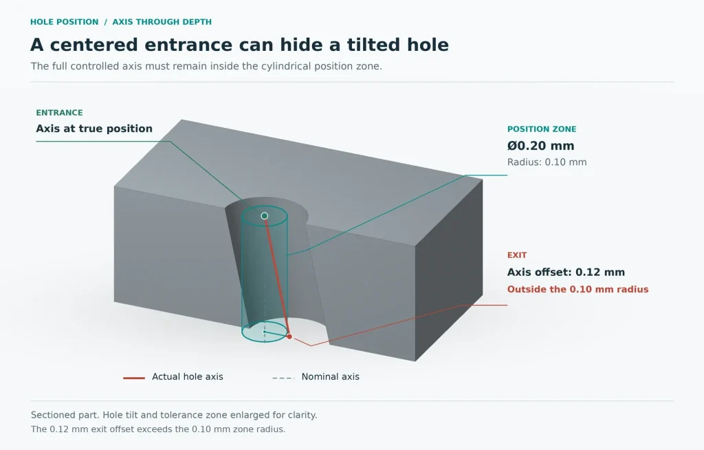
Imagine a straight cylindrical hole whose axis intersects the exact basic location at the entrance but shifts sideways by 0.12 mm at the exit.
With a fixed Ø0.20 mm position zone, the allowable radial distance from the nominal axis is 0.10 mm. The exit lies outside that zone even though the entrance is perfectly centered.
A CMM program that measures only one circle near the entrance can miss this condition.
Position must be evaluated over the controlled feature length, not only at the most accessible cross-section.
The measurement plan should collect data at sufficient depths and around the circumference to establish the feature appropriately. Point distribution matters as well as point count. Repeatedly measuring one small region does not establish the behavior of the entire bore.
Chamfers, burrs, tool marks, and probing access also affect what the collected data represents. A fitted circle at a chamfer transition should not silently become the reported location of the cylindrical hole.
Review the Axis Beyond the Mounting Face
For a pin or fastener that projects beyond the part, the designer may need to consider a projected tolerance zone. Controlling a hole through the plate thickness does not automatically protect clearance farther into the mating component.
For a hole whose nominal axis is perpendicular to the mounting face, let θ be the angle between the actual straight axis and the normal to that face. Over a projection height P, the additional lateral displacement caused by tilt is:
Additional displacement = P × tan θ
Here, P is measured normal to the mounting face, starting at the surface. The displacement acts in the direction of the axis tilt. Any initial position error at the surface must be combined with this displacement as a vector when evaluating the projected axis.
A projected tolerance zone specifies an evaluation region beyond the part surface while retaining the required location and orientation relative to the datums. Its need, starting surface, and height should follow the assembly geometry.
It is not a universal requirement for every threaded or locating hole. The drawing and inspection method must define the feature being evaluated and the region in which its projected axis must comply.
Keep the Hole Pattern in One Permitted Alignment
A hole pattern must be evaluated using the datum relationships and freedoms allowed by its specification.
In the mounting-plate example, the three planar datum references establish the frame. Moving the inspection origin separately for each hole would change the requirement being checked.
The same problem occurs when a free best-fit alignment is used to make the hole pattern look centered while ignoring its relationship to the mounting face and locating edges.
Hexagon’s position-evaluation documentation describes fitting controlled features into their tolerance zones while respecting the datum constraints. Where a pattern has permitted movement, that movement must satisfy the pattern together.
Fitting a measured feature and allowing movement of a reference frame are different operations. Both must match the drawing and the selected verification method.
A material-boundary modifier on a datum reference also needs separate interpretation. Permitted datum mobility is not simply another bonus number to add to every hole’s position tolerance.
Distinguish Composite Position from Stacked Callouts
A composite position specification is not interchangeable with two stacked, independent single-segment position callouts.
In a composite specification, the upper segment establishes the pattern’s location and orientation under its datum references. A lower segment further refines relationships within the pattern and the orientation constraints established by its referenced datums.
The permitted movement of the lower framework depends on those constraints. It is not permission to reposition each hole independently, and it does not remove the upper-segment requirement.
The controlled features must satisfy both segments. Do not treat the lower value as a tighter absolute coordinate tolerance unless that interpretation follows from the actual specification.
Fix the Manufacturing Reference Before Tightening the Hole Size
When position fails, reducing the diameter tolerance may address the wrong problem.
If several holes shift in approximately the same direction, investigate a common cause such as work-offset definition, fixture seating, datum transfer, or an incorrect inspection alignment. If errors vary with hole depth, review axis direction, drilling behavior, tool deflection, and how the bore was measured.
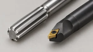
Finishing the diameter does not necessarily correct its location. A conventional reamer generally follows the prepared hole and should not be relied on to relocate an off-position axis. Boring can establish the axis from the setup, provided the starting geometry leaves sufficient cleanup stock. The reaming versus boring guide explains that process boundary.
The manufacturing sequence also matters. Machining the holes before the final datum surfaces are established can leave their relationship vulnerable to later material removal, distortion, or another setup.
Where practical, plan the critical datum features and hole pattern as a connected manufacturing task. If multiple setups are necessary, define how their relationship will be transferred and verified.
Opening a hole to obtain MMC bonus should never be an automatic repair instruction. It must remain within the size limits and preserve the hole’s other functions. Customer approval may also be required for the proposed rework.
Make the Position Report Explain the Result
A useful position report should make it possible to reconstruct the acceptance decision.
For each critical hole or pattern, identify:
- The feature ID and applicable drawing revision.
- The basic location and controlled length.
- The datum references, their order, and any modifiers.
- The stated position tolerance.
- The measured size used for bonus evaluation, where applicable.
- The bonus and total available tolerance.
- The evaluated position deviation and acceptance result.
For the second row of the teaching example, the report should make the relationship clear: 0.300 mm measured position deviation, 0.120 mm bonus, and 0.320 mm total available tolerance.
The inspection plan should also identify how the datums and hole features were established. A report containing only X, Y, and a green result may leave the axis length, size interpretation, and alignment unresolved. The CMM inspection guide covers those broader reporting questions.
For a custom CNC part, send the drawing with its complete position callouts, the mating-part geometry, the intended locating or fastening arrangement, and any available inspection results. Identify whether the hole must provide clearance, precise location, a press fit, or alignment through several components.
Through our CNC machining services, Rapid Efficient can review the datum strategy, hole-making sequence, and inspection requirements before quotation.