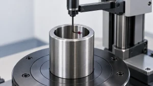
A machined sleeve can have round cross-sections and acceptable bore diameters while still failing its cylindricity requirement. The missing information is how those sections form one continuous surface along the bore.
Cylindricity controls the form of an entire cylindrical surface. That surface must fit between two coaxial cylinders separated by the specified radial distance. The requirement does not use a datum, and it does not establish the bore’s location relative to mounting faces or other holes.
For a buyer or inspector, the practical question is whether the measurement covers the surface that the drawing controls. A diameter reading, a roundness result, and a cylindricity result answer different questions.
Read the Cylindricity Value as a Radial Gap
The cylindricity symbol is ⌭. A callout combining this symbol with 0.010, on a drawing using millimeters, specifies a tolerance zone with a radial thickness of 0.010 mm.
The two bounding cylinders share one straight axis. Their radii differ by the tolerance:
Tolerance-zone thickness = outer-cylinder radius − inner-cylinder radius
Mitutoyo’s geometric tolerance-zone illustrations show this distinction between a cylindrical surface zone and other geometric tolerance zones.
The value is not a ±0.010 mm diameter allowance. It also does not describe a solid cylinder of diameter 0.010 mm in which the bore axis must lie. The controlled object is the surface.
A standard cylindricity callout has no datum reference and does not gain bonus tolerance as the feature departs from maximum material condition. The drawing still needs separate size limits, along with any location or orientation controls required by the assembly. Applicable size-envelope requirements also remain relevant.
Surface texture is another separate requirement. A surface can have low roughness yet remain tapered or barrel-shaped.
Round Sections Can Form a Barrel-Shaped Bore
Consider an illustrative sleeve with these drawing requirements:
- Bore diameter: 20.000–20.040 mm
- Controlled cylindrical length: 60 mm
- Cylindricity tolerance: 0.010 mm
Assume the bore is axisymmetric: every cross-section is a perfect circle, all section centers lie on one straight axis, and the diameter changes smoothly along the length. The smallest diameter occurs near the ends, and the largest occurs at the middle.
These are hypothetical dimensions for explaining the geometry, not production results or machining capability claims.
| Position along the controlled surface | Section diameter | Section radius |
|---|---|---|
| Near the entrance | 20.010 mm | 10.005 mm |
| Middle | 20.034 mm | 10.017 mm |
| Near the far end | 20.010 mm | 10.005 mm |
Every diameter is within the stated size limits. Every section has zero circularity error in this idealized model.
However, the cylindrical surface requires a radial zone of:
10.017 − 10.005 = 0.012 mm
The bore therefore exceeds the 0.010 mm cylindricity tolerance by 0.002 mm.
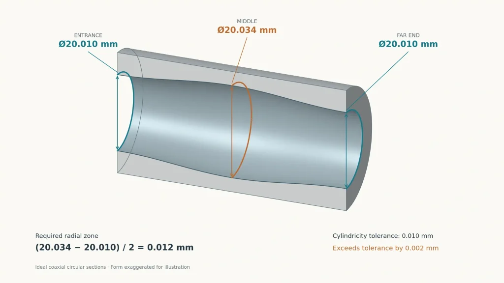
The middle section is larger, so the bore has a barrel-shaped internal profile. Each section can be round while the complete surface requires a wider cylindrical zone.
Circularity evaluates individual sections; cylindricity evaluates the surface through the controlled length.
For this particular model, the radial form difference equals half the diameter spread:
(20.034 − 20.010) ÷ 2 = 0.012 mm
Do not apply that shortcut to an arbitrary measured bore. Lobing, displaced section centers, and a curved center path require evaluation of the surface points together. A list of maximum and minimum diameters cannot capture all those conditions.
Keep the Form Axis Separate from the Assembly Axis
The coaxial cylinders used to evaluate cylindricity are fitted to the controlled surface. Their axis is not automatically the assembly’s datum axis.
A geometrically perfect bore can be tilted relative to a mounting face and still have zero cylindricity error. Two separate bores can each satisfy cylindricity while failing their required alignment.
This distinction matters when a drawing is intended to control bearing seats, locating bores, or rotating journals. The designer needs to identify whether the functional concern is the shape of one surface, its relationship to another feature, or both.
Total runout introduces a datum-axis relationship. Cylindricity evaluates the form independently of that relationship. Our concentricity and runout guide explains those adjacent controls.
Using a fitted axis for a datum-free form calculation is appropriate. Removing a required datum relationship from a separate position or runout evaluation is a different action and can invalidate that result.
Choose Measurement Paths That Can Reveal the Error
A dedicated form-measuring instrument or a suitable CMM can evaluate cylindricity. The instrument name alone does not establish whether the measurement is sufficient.
The plan needs circumferential coverage around the feature and axial coverage along it. Choose the paths from the bore geometry and the form errors that the process could produce.
| Surface condition to investigate | What a limited check can miss | Measurement coverage to review |
|---|---|---|
| Barrel or hourglass shape | End diameters can agree while the middle differs | Sections through the middle and intermediate depths, supported by axial coverage |
| Bell-mouth near an entrance | A measurement taken farther inside may miss the enlarged region | Closely spaced measurements near the cylindrical end, with chamfers and edge exclusions defined |
| Lobing around a section | A few contact directions may miss peaks and valleys | Circumferential traces or sufficiently dense angular sampling |
| Curved or drifting center path | Separate roundness results can conceal the relationship between sections | Surface data from multiple depths evaluated together in one cylinder-form calculation |
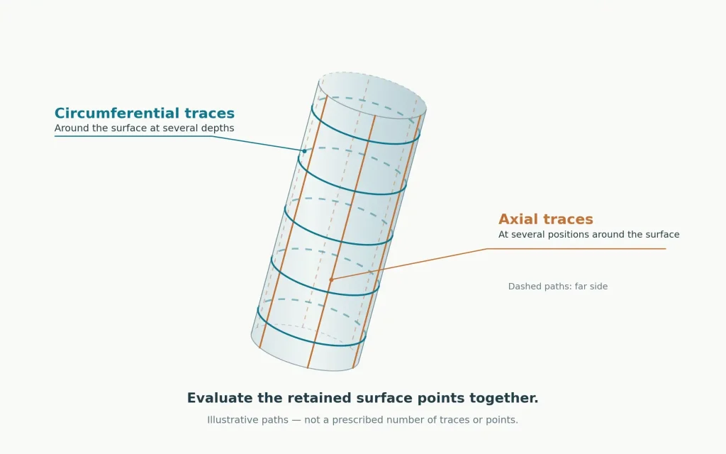
There is no universal number of sections or points that proves every bore. The necessary coverage depends on feature length, expected error pattern, tolerance, access, and measurement uncertainty.
A calibrated two-point bore gauge is useful for checking local size and detecting certain changes with depth. It does not reconstruct the complete cylindrical surface. Likewise, passing a plug gauge can verify the boundary for which that gauge was designed without producing a separate cylindricity value.
For a blind bore, confirm how close the stylus can reach to the bottom and which surface is actually controlled. An inaccessible region should not silently disappear from the acceptance requirement.
Keep the part clean and thermally stable. Handling and temperature differences along a sleeve can affect the measurement. Establish the stabilization time from the part, environment, and required uncertainty rather than assuming one waiting period suits every component.
For a thin sleeve, define the support or restraint condition. A measurement taken while the sleeve is distorted by a fixture may not represent its released shape.
Evaluate the Surface Points Together
A CMM can report several good roundness results without having evaluated cylindricity. Reporting only independently fitted circles leaves their relationship to a shared cylinder unevaluated.
Retain the surface data and apply the intended cylinder-form calculation. Hexagon’s cylindricity evaluation documentation explains how sampling and fitting affect the reported result.
A minimum-zone calculation seeks the two coaxial cylinders with the smallest radial separation that enclose the measured points. A least-squares fit minimizes squared deviations from a reference cylinder instead.
For the same retained points, the radial spread about a least-squares axis cannot be smaller than the minimum-zone optimum. Fitting, filtering, and rejecting points are separate operations; they should not be treated as interchangeable explanations for a different result.
A better fitting routine cannot recover a surface peak that was never measured.
When comparing supplier and customer reports, review:
- The controlled length and any excluded regions.
- Section locations, angular sampling, and scan paths.
- The cylinder-fitting and evaluation method.
- Filtering and treatment of rejected points.
- Part support, temperature, and measurement uncertainty.
Do not change those settings merely to obtain a passing number. Near the tolerance limit, apply the agreed acceptance rule with the measurement uncertainty understood.
The CMM inspection guide provides broader guidance on connecting report results to the drawing requirements.
Correct the Shape Before Adjusting the Diameter
The barrel-bore example also explains why a uniform diameter offset may fail to solve the problem.
In the simplified model, increasing every diameter by the same amount moves both limiting radii outward equally. Their difference remains 0.012 mm. The size changes, but the form error does not.
Before choosing a corrective operation, establish where the surface departs from the required cylinder. A repeatable taper, an enlarged entrance, and a lobed section need different investigations. Relevant factors may include tool deflection, support, clamping distortion, tool condition, or the finishing tool’s contact along the bore.
Thin sleeves can deform under localized jaw pressure and change shape when released. Depending on the geometry, distributing the clamping contact, reducing clamping force, or using a suitable axial clamping arrangement may help. Compare the clamped and released form before treating the cutting tool as the only source of error.
Honing may correct selected bore-form errors when the tooling, allowance, and geometry support that correction. It also removes material. In the example, bringing the smaller sections toward the larger middle could improve form, but the final bore must still meet its upper size limit.
The honing process guide explains why the incoming error and available stock matter when planning that route.
The drawing should identify the cylindrical surface and controlled extent clearly. Separate bearing lands, relief grooves, chamfers, and interrupted regions may need clarification. Confirm whether acceptance applies after heat treatment, coating, or another operation that can change the final surface.
For a cylindricity-critical part, share the bore or shaft diameter limits, controlled length, wall thickness, and any existing form report. Through our CNC machining services, RapidEfficient can review the proposed machining sequence and inspection requirements before quotation, including whether the available measurement access supports the specified control.