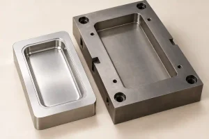
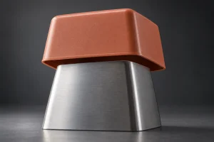
Draft changes the size of a molded feature along its depth. An opening can meet its width requirement at the rim and still be too narrow for a component that must slide farther inside.
An injection molding draft angle is the taper applied to a surface to help it separate from the forming steel. For a simple straight wall, the angle is measured relative to the release direction. The drawing also needs to establish where the feature’s size applies.
Choose the release direction and the section that must retain its functional size together. Then check the resulting geometry through the full mating depth. A general note such as “1° draft” leaves that dimensional decision unresolved.
Follow the Surface in Its Release Direction
Begin with the relative motion between the plastic and the steel forming each surface. For an open housing, the core must leave through the opening. An internal pocket that becomes wider toward that opening can provide clearance during withdrawal.
A side hole formed by a sliding core has a different release direction. Review its surfaces against that core’s travel, rather than applying the main mold-opening direction to the whole part.
Draft also cannot remove an unchanged shoulder that physically traps the core. Our undercut release guide covers the separate decision about how to clear those obstructions.
How much draft is enough? Protolabs’ draft-angle guidance gives 1–2° as a useful general range while explaining that material, depth, finish, geometry, and tooling change the requirement. Treat such guidance as a starting point for a specific surface.
A smooth, shallow feature and a deep textured wall may need different allowances for release. A feature that shrinks onto a core can also behave differently from an outside surface separating from a cavity.
For textured areas, review the selected finish with the release geometry. The injection molding surface finish guide addresses that relationship in more detail.
What One Degree Changes in a 40 mm Opening
Consider an illustrative rectangular pocket with two opposing flat walls. The pocket narrows inward, and each wall has 1° of draft relative to the withdrawal direction.
Let:
- \(W_0\) be the width at the opening plane.
- \(z\) be depth measured inward from that plane, parallel to the withdrawal direction.
- \(\alpha\) be the draft angle on each wall.
The inward movement of one wall is \(z\tan\alpha\). Because both walls move inward, the width is:\[ W(z)=W_0-2z\tan\alpha \]
For an opening width of 40.000 mm:
| Depth from the opening plane | Inward movement per wall | Width between the walls |
|---|---|---|
| 0 mm | 0.000 mm | 40.000 mm |
| 10 mm | 0.175 mm | 39.651 mm |
| 20 mm | 0.349 mm | 39.302 mm |
Values are rounded after calculation. The example assumes ideal flat walls, equal draft on both sides, and measurement sections clear of corner radii. It does not include molding variation, warpage, or shrinkage compensation in the tool.
At 20 mm depth:\[ W(20)=40.000-2(20)\tan(1^\circ)\approx39.302\text{ mm} \]
Suppose a rigid, straight-sided mating component is 39.400 mm wide and must reach that section. It clears the 40.000 mm opening, but exceeds the nominal width at 20 mm depth by approximately 0.098 mm. Passing through the entrance does not establish clearance through the required travel.
The relevant fit is the clearance along the mating path, including the narrowest required section.
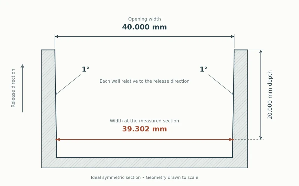
The factor of two belongs to this two-sided, equal-angle example. If only one wall moves, or the walls have different angles, calculate their contributions separately. Curved walls and changing draft require evaluation of the actual section geometry.
Choose the Section That Must Keep Its Size
Adding draft in CAD requires a decision about which geometry stays fixed. In a simple neutral-plane draft, the wall pivots about its intersection with the selected plane.
That modeling choice affects the rest of the feature. Holding the opening at 40.000 mm produces the narrowing shown above. If the design instead requires a nominal width of 40.000 mm at 20 mm depth, the opening must become:\[ W_0=40.000+2(20)\tan(1^\circ)\approx40.698\text{ mm} \]
The same angle creates a different part because a different section retains the specified size. Increasing the opening may affect the cover overlap, outside envelope, or remaining wall thickness.
Identify the surface or assembly interface that actually controls the fit before choosing the fixed section. The mold parting plane, a CAD neutral plane, and an inspection datum serve different purposes; they should not be assumed to coincide.
A drawing for the pocket could identify a rim seating face as datum A and locate the required width section 20 mm inward from that reference. The released definition then needs the width tolerance, taper direction, and appropriate angle or surface controls. Specify any required control of the section’s location as well as its width.
Where a radius removes a physical sharp edge, clarify whether a dimension refers to an actual surface section or a theoretical intersection. Otherwise, the CAD model and the inspection program may evaluate different locations.
Draft belongs in the nominal geometry; it is not extra manufacturing variation that a size tolerance automatically absorbs.
Avoid assigning independent tolerances to the opening width, lower width, depth, and angle without checking that the requirements agree. Establish the controlling requirements and identify derived dimensions appropriately under the drawing convention used.
A molded bore needs the same reasoning. If a core pin gives the hole a taper, define the diameter at the relevant depth and check the required engagement length. A single diameter reading near the mouth cannot describe the entire tapered hole.
Give Ribs and Close Fits Their Own Draft Review
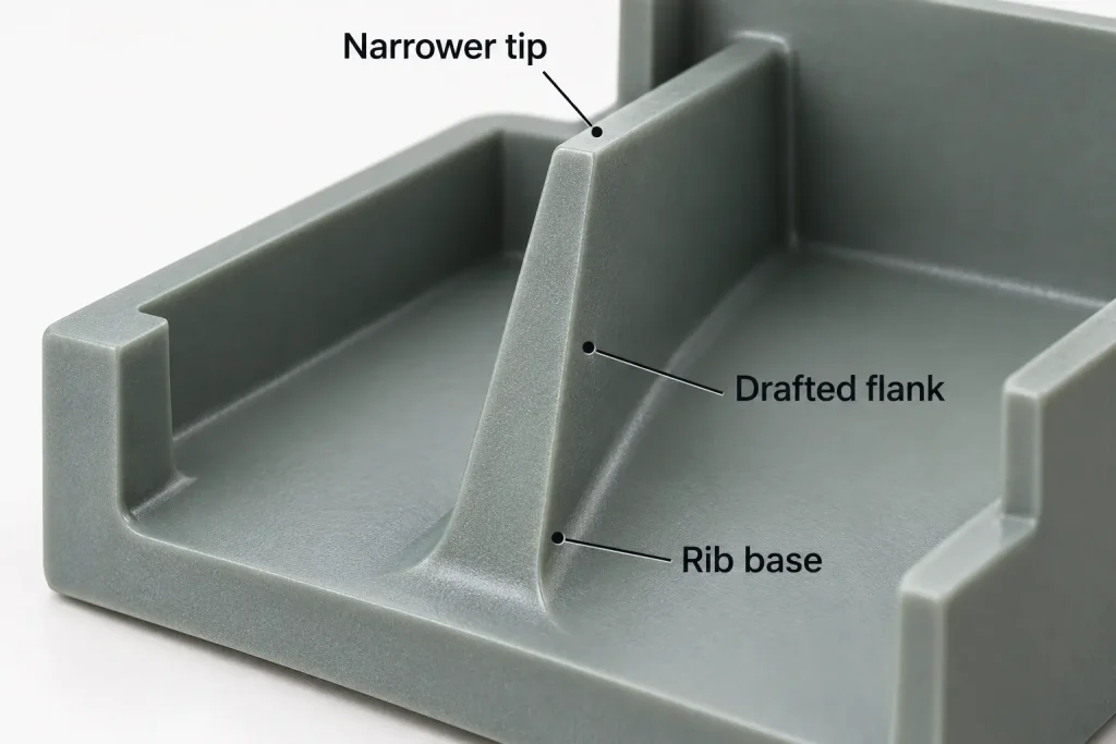
The taper that opens a pocket can reduce the top thickness of a rib. Copying an angle from the housing wall onto every feature may therefore change stiffness, filling conditions, or available contact area.
For an ideal rib with straight flanks, fixed base thickness \(b\), height \(h\), and inward draft \(\alpha\) on each side:\[ t_{\text{top}}=b-2h\tan\alpha \]
As a geometry example, a 1.500 mm base thickness, 20 mm height, and 1° draft per side give a top thickness of approximately 0.802 mm. This calculation excludes root and tip radii and is not an approved rib design or a mold-filling prediction.
Covestro’s Part and Mold Design guide discusses how draft can leave tall rib tips too thin to fill readily. Review the resulting section against the selected resin, tool, and structural requirement rather than accepting the angle alone.
Check the rib’s remaining tip thickness after adding draft, not only its thickness at the base.
On a hollow wall, review both the inside and outside surfaces. Drafting one while leaving the other unchanged can create a thickness change over the height. That change may affect cooling and deformation as well as the available space.
Close-fitting surfaces deserve separate treatment. A locating band, sliding guide, or sealing contact may have little room for taper. Identify the required contact length and permitted clearance before deciding how to form it.
Possible approaches include reducing the functional contact length, changing the local release arrangement, or machining a selected surface after molding. Each approach requires a tooling and cost review. A nearly straight feature should be treated as a specific manufacturing requirement, with an agreed release method, rather than accepted because a CAD draft analysis shows no obvious interference.
Measure the Taper at the Specified Depth
The inspection method should evaluate the same section defined by the drawing. “Check the pocket width” is incomplete when the width changes with depth.
In the 1° pocket example, moving the measurement section by 1 mm changes the nominal width by:\[ 2(1)\tan(1^\circ)\approx0.035\text{ mm} \]
Two readings can therefore differ because they were taken at different heights, even when the walls follow the intended geometry.
Calipers may contact a tapered pocket at an uncertain depth or touch a radius instead of the straight wall. Use a suitable depth-controlled arrangement when that method can meet the inspection requirement. Check contact force as well; squeezing a flexible housing changes the feature being measured.
For CMM inspection, establish the specified datum alignment and evaluate the surfaces at the required section. The report should identify the section depth and the method used to construct or measure it. An average width derived from an unspecified area should not replace the required local dimension.
Measurements at several depths can help separate a nominal taper from bowed walls or a local restriction. A few sections still do not prove every point of the mating path is clear. Where assembly depends on that path, an agreed functional gauge or mating-part test can complement dimensional inspection.
The CMM inspection guide explains how to connect measured features, datum alignment, and report scope. For flexible or moisture-sensitive molded parts, also agree on the support and conditioning state used for acceptance.
Before approving the tool, make the model, drawing, and inspection plan refer to the same drafted surfaces and measurement sections. Review molded samples for release damage and for the fit that the draft was intended to preserve.
For a draft review through our injection molding services, share the model with the proposed release directions, the mating component and insertion depth, and the sections where dimensions must hold. Include the resin grade and surface finish. RapidEfficient can review those requirements with the proposed tooling route before quotation.