
For CNC parts, a steel vs aluminum comparison starts with whether the geometry can change. Aluminum can reduce mass, but a direct substitution can also increase elastic movement. Steel may suit a compact part with limited room to increase its section; aluminum becomes a different proposal when the design allows a thicker wall, a deeper rib, or a shorter unsupported span.
A buyer comparing two quotations therefore needs to know whether both suppliers are pricing the same drawing or whether one price depends on a redesign. A lighter part that moves a locating surface too far under load has not met the original requirement.
This comparison concerns carbon and low-alloy steels versus aluminum for machined structural parts. If stainless steel is being considered for corrosion resistance or another specific requirement, use the separate aluminum versus stainless steel comparison.
Decide Which Dimensions the Material Change Can Touch
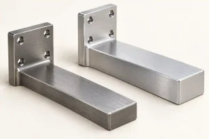
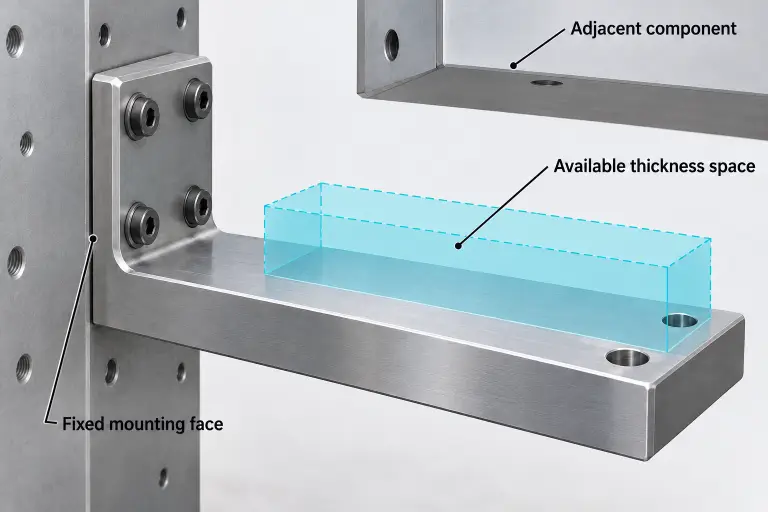
Consider a support bracket with a fixed mounting face and a projecting arm that carries a locator. Its bolt pattern may be fixed by the machine, while the arm thickness can change within an available clearance. Those are different design constraints.
If every surface must remain in its original position, the supplier can compare manufacturing costs for the two materials, but that comparison does not establish equivalent structural behavior. The designer still needs to check the selected grades and conditions against the load and permitted movement.
If the arm may grow thicker, the aluminum option can be assessed as a revised part. Mark the mounting faces, hole positions, tool access, and surrounding clearance that must remain unchanged. Also identify the direction in which material can be added. Increasing a dimension in the wrong direction may provide little benefit for the bending that matters.
Separate the unchanged-drawing quotation from the redesigned aluminum quotation. Each needs its own defined geometry and acceptance requirements.
Grade and condition belong in that definition. An as-rolled structural steel, a hardened alloy steel, and a heat-treated aluminum plate are not interchangeable purchasing descriptions. Strength, wear behavior, and machining requirements depend on the actual material being supplied.
Higher yield strength also does not necessarily mean less elastic bending. Yield strength concerns the onset of permanent deformation; elastic deflection depends on stiffness. Selecting a stronger grade within a material family may improve the first limit without making a substantial improvement to the second.
Compare the Same Shape and the Same Bending Stiffness
A simple strip calculation shows why the comparison condition matters. It is an illustrative design calculation, not a tested bracket or a recommended minimum thickness.
Assume a rectangular cantilever strip with a free length of 100 mm and a width of 20 mm. The steel strip is 6.000 mm thick. Apply the same transverse end load with the same ideal fixed support, bending through the thickness. Assume small deflection and that both materials remain elastic. Ignore self-weight loading and support compliance.
For the steel example, use S355JR in the as-rolled condition. Ovako’s S355JR data sheet gives typical values of 210 GPa for Young’s modulus and 7.80 g/cm³ for density. For a 6061-T651 plate alternative, use the reference physical values in thyssenkrupp’s EN AW-6061 data sheet: 70 GPa and 2.70 g/cm³. These are calculation inputs, not acceptance limits for every product carrying those grade names.
For this rectangular section:
I = b × t³ ÷ 12
Here, I is the second moment of area, b is the width, and t is the thickness in the bending direction. With the load, free length, and support unchanged, the ideal bending deflection is inversely proportional to E × I, where E is Young’s modulus.
Changing only the material therefore makes the same-sized aluminum strip deflect three times as much in this model: 210 ÷ 70 = 3.
To match the steel strip’s bending stiffness while keeping the width and free length unchanged:
Aluminum thickness = 6.000 × cube root of (210 ÷ 70) ≈ 8.653 mm
| Comparison condition | Material and condition | Thickness | Mass of the free strip | Relative bending deflection |
|---|---|---|---|---|
| Starting geometry | S355JR, as rolled | 6.000 mm | 93.6 g | 1.000 |
| Same geometry | 6061-T651 | 6.000 mm | 32.4 g | 3.000 |
| Same ideal bending stiffness | 6061-T651 | 8.653 mm | 46.7 g | 1.000 |
Mass excludes the mounting region, fasteners, and other features. The last row uses the unrounded calculated thickness; displayed thickness, mass, and deflection ratios are rounded.
The aluminum strip retains a mass advantage at equal bending stiffness, but it needs additional thickness to achieve that result.
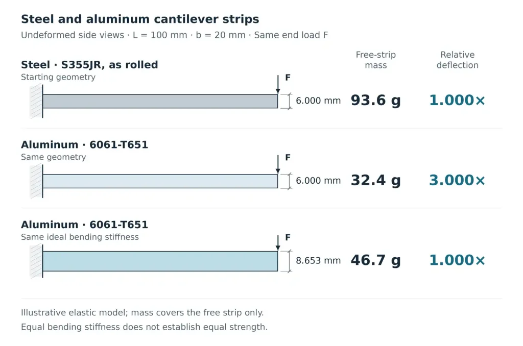
In this example, the thicker aluminum strip weighs about half as much as the steel strip. That differs substantially from the same-geometry comparison, where the aluminum strip weighs about one-third as much. Neither result applies automatically to a complete bracket.
An actual component may have holes, root fillets, changing sections, flexible mounting points, or a different load direction. A ribbed section can use material differently from a solid strip. Local bearing, yielding, fatigue, and buckling also require their own checks. Matching this one bending-stiffness value does not prove equal load capacity or service life.
Include the Contacts That Keep the Assembly Working
The arm’s movement is only part of the bracket’s function. A locating bore, a clamped joint, or a frequently used thread can control whether the material change works in service.
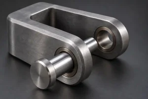
A steel pin running directly in an aluminum bore creates a different contact from the original steel arrangement. Depending on loading, lubrication, and required life, the design may need a replaceable bushing or another wear surface. That adds a component, a seat to machine, and an assembly requirement. Its mass belongs in the finished assembly comparison.
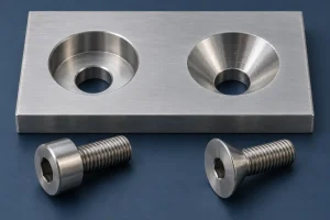
Likewise, a threaded hole should be reviewed against the screw size, engagement, installation load, and number of assembly cycles. A steel insert may be appropriate, but it is not an automatic requirement for every aluminum thread. If an insert is specified, the quotation should include its seat, installation, and any retention check the drawing requires.
Clamped faces deserve attention as well. Review the bearing area under the fastener and the permitted local deformation. A washer or revised boss can affect both the available space and the machining route.
Finishing choices must follow these functions. A hard surface treatment does not give an aluminum arm the bulk stiffness of a steel arm. A coating can also change a fitted bore or seating surface, so define whether critical dimensions apply before or after finishing. In a wet assembly containing aluminum and steel, review galvanic corrosion and the required isolation or protection of the joint.
These features can make a heavier body with simple contacts competitive with a lighter body that needs additional hardware. Compare the complete working arrangement rather than only the mass of the machined body.
Compare the Stock and Process Route Behind the Price
The equal-stiffness calculation describes finished geometry. A supplier buys a blank with machining allowance, not exactly 46.7 g of material.
The thicker aluminum design may require a different plate size. A ribbed design may reduce finished mass while leaving more material to remove from the blank. Stock availability, minimum purchase quantities, and how parts are arranged in the stock can therefore change the quotation even when the finished CAD volume is lower.
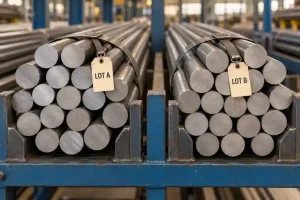
Specify the product form and supply condition as well as the grade. For aluminum plate, the 6061-T6 versus T651 guide explains why the temper designation and stress-relief condition matter. A suitable stock condition can help the manufacturing plan, but it does not remove the need to consider material removal, workholding, and dimensional movement.
Machining time is another separate term. An aluminum part may permit a productive cutting route, yet deep pockets, thin walls, repeated setups, or inserted components can offset that advantage. Steel machining cost also changes with grade and hardness. Neither a material price per kilogram nor a generic machinability ranking establishes the finished-part price.
Keep the quotation alternatives explicit:
| Quotation alternative | What the supplier should price | What still needs approval |
|---|---|---|
| Retain the steel design | Specified steel condition, current geometry, finishing, and inspection | Whether the current part meets the weight and functional targets |
| Substitute aluminum without changing the shape | The same geometry in a specified aluminum grade and temper, with stated finishing and hardware | Deflection, strength, contacts, and assembly suitability of the substitution |
| Redesign the part for aluminum | Revised geometry, suitable blank, machining, inserts or bushings, finishing, and inspection | The revised part’s function and its fit within the permitted space |
A lower quotation is comparable only when its geometry, delivery scope, and approval assumptions are visible.
If the original is a welded steel fabrication and the alternative is machined from one aluminum block, the comparison includes a manufacturing-route change. Account for the original cutting, welding, and finish machining alongside the alternative blank and machining operations. If welding remains in the aluminum route, the joint review must use appropriate weld-region properties rather than simply carrying over the unwelded stock’s strength.
Separate one-time work from repeat production costs. A new fixture, design review, or agreed validation program can matter in a small order. Request both alternatives at the same quantity and delivery scope so those costs are visible rather than hidden in different unit-price assumptions.
Approve the Revised Part Where It Is Used
A dimensional report can confirm that the supplier made the revised drawing. It cannot by itself show that the locator stays within its permitted movement when the bracket is loaded.
Define the functional evidence before approving the substitution. For the support bracket, that may mean measuring locator displacement under a specified load and checking for permanent movement after unloading. A repeatedly loaded or sliding feature may also need fatigue or wear evidence appropriate to its intended use. Select the conditions and limits from the application; the strip calculation does not supply them.
Verify the complete assembly, including fasteners, bushings, and finishing. Check that the thicker arm clears nearby components and that installation tools still reach the fasteners. Record the drawing revision, material condition, and finishing state used for approval so the production order refers to the same configuration.
For a CNC machining review, provide the current steel drawing, candidate aluminum grade and temper, quantity, and the surfaces that must remain fixed. Identify the space available for a thicker section, the relevant loads and permitted movement, and any wear contacts or threaded connections. These details support a manufacturing and quotation review of both the original part and the proposed alternative; structural approval should remain tied to the application’s design requirements.