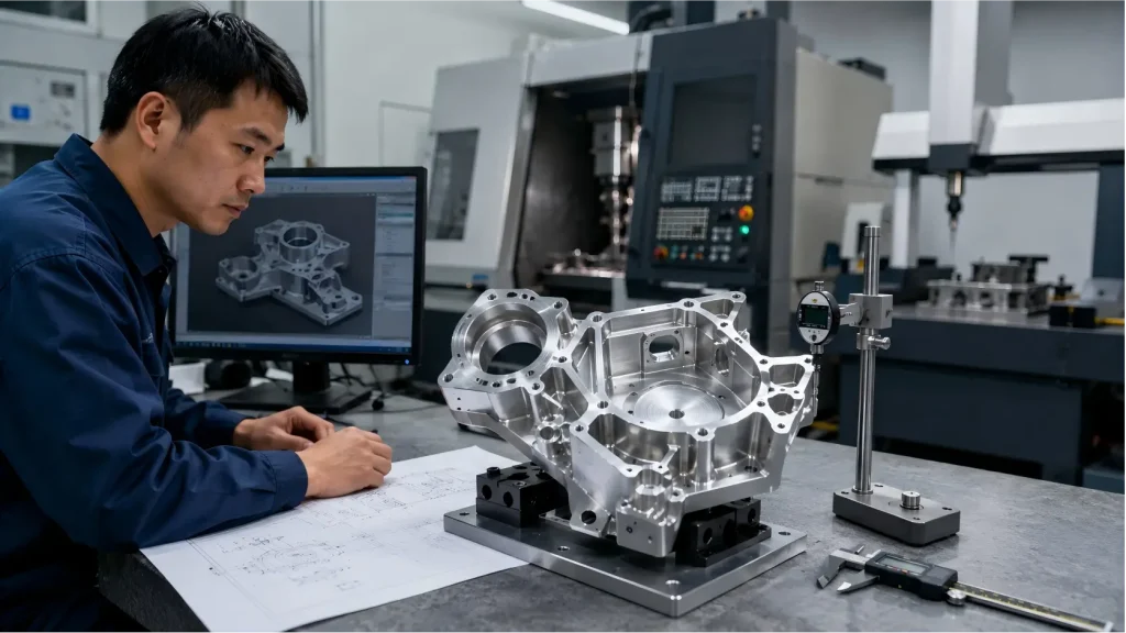
A complex CNC part is not difficult simply because its outside shape looks unusual.
Some visually complex parts are straightforward once they have stable clamping surfaces and accessible features. At the same time, a simple-looking housing or bracket may be difficult because it contains thin walls, deep pockets, angled holes, limited datum surfaces, or tight relationships between features machined in different setups.
The main challenge is usually not creating the CAD model.
The real challenge is creating a machining and inspection plan that keeps the part stable, preserves functional relationships, gives the cutting tool enough access, and allows the finished geometry to be measured correctly.
For complex-shaped CNC parts, engineering review should begin before tooling, fixtures, and machining sequences are finalized.
Quick Answer
Complex-shaped CNC parts often require more planning because they may have:
- Limited clamping surfaces
- Features on several faces
- Angled holes or undercuts
- Thin walls and ribs
- Deep pockets
- Long tool-reach requirements
- Datums that must transfer between setups
- Critical features that are difficult to measure
- Different dimensions in the clamped and free states
A reliable process usually depends on five connected decisions:
- How the part will be held
- Which datums will control each setup
- Which features should be machined together
- Whether three-axis, indexed multi-axis, or simultaneous five-axis machining is appropriate
- How the finished part will be aligned and inspected
Five-axis machining may reduce some setup transfers, but it does not automatically solve poor fixturing, weak datums, tool deflection, distortion, or inspection-access problems.
What Makes a CNC Part Complex?
“Complex-shaped” does not have one universal geometric definition.
In CNC machining, complexity is better evaluated from manufacturing risk than from appearance alone.
A part may become difficult when it contains one or more of the following conditions.
Features on Multiple Faces
A component may have:
- Holes on opposite sides
- Angled mounting faces
- Side slots
- Cross-drilled passages
- Counterbores on different orientations
- Multiple mating interfaces
- Bores that must remain aligned across the part
The difficulty comes from maintaining relationships between those features, especially when they cannot all be completed in one setup.
Limited Workholding Surfaces
Some parts do not provide a stable flat surface for a vise, chuck, or fixture plate.
Other parts lose their original clamping surfaces as machining progresses.
This may require:
- Temporary machining stock
- Sacrificial tabs
- Custom soft jaws
- Fixture plates
- Locator pins
- Clamping bosses
- Vacuum or adhesive-assisted holding
- A dedicated second-operation fixture
Deep or Obstructed Geometry
Deep pockets, recessed holes, narrow channels, and hidden features can limit access for both cutting tools and inspection probes.
The nominal geometry may be possible to model but impractical to machine with a rigid tool.
Thin Walls and Flexible Sections
Thin walls, ribs, fins, long arms, and open frames may move under:
- Clamping force
- Cutting force
- Tool pressure
- Heat
- Residual-stress release
- Part handling
The feature may measure differently while clamped than after the fixture is released.
Difficult Datum Relationships
The drawing may require one feature to remain accurately related to another feature located on a different face.
Examples include:
- A bore axis relative to a mounting plane
- An angled hole relative to an external profile
- Two opposing bearing bores
- A slot relative to a sealing surface
- Multiple mounting faces controlled by one datum system
These relationships may be more difficult than the individual dimensions themselves.
Inspection Constraints
Some complex surfaces are hard to access with standard gauges.
A part may require:
- CMM inspection
- Custom inspection fixtures
- Scanning
- Probe-angle planning
- Sectioned inspection routines
- Free-state inspection
- Restrained inspection
- Comparison against the CAD model
A part should not be considered manufacturable until it can also be inspected.
Workholding Is Often the First Engineering Problem
Before selecting a toolpath, the process planner must determine how the part will be held without blocking important features or deforming the workpiece.
The best fixture is not always the strongest fixture.
A fixture must provide enough support and repeatability while avoiding unnecessary clamping force.
Standard Vise and Soft-Jaw Workholding
A standard vise may work when the raw material provides:
- Parallel gripping faces
- Enough material below the finished profile
- Reliable support against cutting forces
- Access to the required top and side features
Custom soft jaws can improve location and support for irregular geometry.
Soft jaws may be machined to match:
- Curved profiles
- Stepped surfaces
- Existing bores
- Partial finished geometry
- A second-operation shape
However, soft jaws require enough contact area and a stable locating strategy. A detailed jaw profile does not automatically prevent part movement.
Fixture Plates and Modular Workholding
Fixture plates can support parts that require multiple locators, clamps, stops, or support points.
They may be useful for:
- Large plates
- Asymmetric housings
- Repeated low-volume production
- Multiple parts in one setup
- Components with no suitable vise surface
- Parts requiring known locator positions
The fixture should distinguish between:
- Locating the part
- Supporting the part
- Clamping the part
Using every contact point as a hard locator can over-constrain the component and make loading inconsistent.
Temporary Datums and Sacrificial Features
The finished part may not contain a practical clamping surface.
In that case, temporary features can be added to the manufacturing model, including:
- Extra stock around the profile
- Machining tabs
- Temporary bosses
- Sacrificial holes
- Fixture rails
- Extended base material
- Removable clamping ears
These features are removed during a later operation.
Temporary features increase material and machining time, but they can provide a more stable and repeatable process than attempting to grip the final geometry directly.
They should be planned before stock size and toolpaths are finalized.
Vacuum, Adhesive, and Auxiliary Holding
Vacuum fixtures may support thin plates or broad flat components when enough sealing area is available.
Their effectiveness depends on:
- Contact area
- Surface flatness
- Seal design
- Leakage
- Cutting direction
- Material-removal sequence
- Remaining wall thickness
Vacuum holding may be unsuitable for a small part with limited sealing area or aggressive side cutting.
Adhesive, wax, or temporary bonding methods may help with thin or delicate components, but removal, cleaning, temperature, and surface compatibility must be considered.
These methods are project-specific and should not replace proper mechanical support when cutting forces are high.
Avoiding Clamping Distortion
A part may be machined accurately while clamped but fail after release.
This can happen when:
- Thin walls are compressed
- A bowed blank is forced flat
- Supports are positioned unevenly
- Clamps are tightened in an inconsistent sequence
- The part is over-constrained
- Large amounts of material are removed from one side
- Residual stress is released during machining
Possible controls include:
- Reducing clamping force
- Increasing the number of light support points
- Supporting close to the cutting area
- Using controlled clamp torque
- Roughing the part before final fixturing
- Releasing and reclamping before finishing
- Inspecting the component in the required state
The correct method depends on geometry, material, stock condition, and functional requirements.
Datum Planning Across Multiple Setups
A complex part may pass through several machining operations.
Each setup must reproduce the intended relationship between the cutting tool and the drawing datum system.
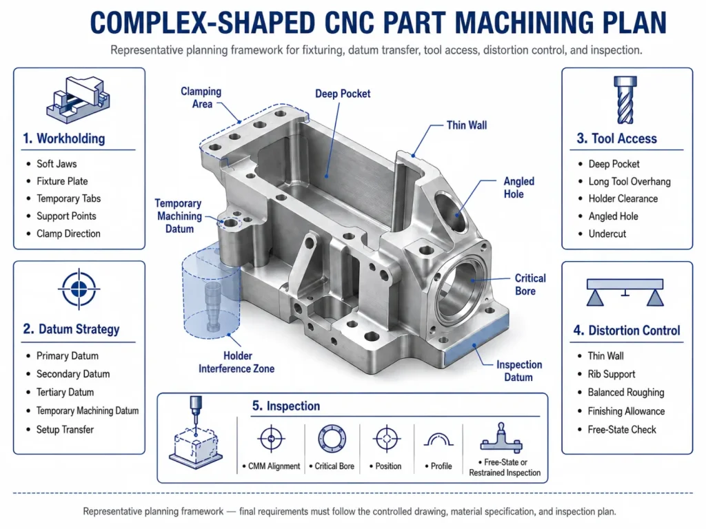
Small errors from individual setups can combine into a larger functional error.
Primary, Secondary, and Tertiary Datums
A datum system typically removes the part’s available movement in a controlled sequence.
In practical fixturing:
- The primary datum establishes the main orientation.
- The secondary datum controls another direction.
- The tertiary datum completes location.
The selected datum surfaces should be:
- Functionally relevant
- Stable enough to contact
- Accessible during machining or inspection
- Clearly identified on the drawing
- Repeatable between setups
A small cast, curved, flexible, or unfinished surface may be a poor manufacturing datum even when it appears convenient in the CAD model.
For more detailed discussion of functional dimensions and datum relationships, review our CNC machining tolerances guide.
Machining Datums Versus Design Datums
A design datum is defined by the drawing.
A machining datum is used to locate the part during production.
They are not always the same physical feature.
Temporary machining datums may be required when:
- The design datum does not yet exist
- The final datum is too small for stable location
- The datum becomes accessible only after roughing
- The design datum will be machined away
- A fixture needs additional control during early operations
The process plan should explain how the machining coordinate system will eventually be transferred to the final design datums.
Without this plan, a part may be internally consistent within one setup but incorrect relative to its finished functional references.
Datum Loss
Datum loss occurs when a feature used for earlier location is removed, altered, or covered during later processing.
Examples include:
- Machining away the original stock surface
- Removing a temporary boss
- Coating a locating diameter
- Finishing a face that previously contacted the fixture
- Cutting the final outer profile from a fixture frame
Before removing a datum, the next setup must have another reliable reference.
This may be created through:
- Finished holes
- Reamed pin locations
- Controlled bores
- Mating faces
- Probed surfaces
- Temporary reference features
The handoff between datums should be planned rather than improvised after the first operation.
Probe Verification Between Setups
Machine probing can help verify:
- Part location
- Fixture position
- Orientation
- Stock variation
- Reference surfaces
- Selected bore centers
Probing is useful for confirming setup conditions, but it does not correct every source of error.
Probe results can still be affected by:
- Surface condition
- Burrs
- Dirt
- Probe calibration
- Stylus access
- Part movement
- Thermal conditions
- Incorrect alignment logic
Probing should support a sound datum and fixture strategy, not replace one.
Which Features Should Be Machined Together?
Features with important positional or angular relationships may benefit from being machined in the same setup.
Examples include:
- Multiple bores sharing one axis relationship
- A bore and its perpendicular mounting face
- Angled holes related to a central datum
- Mating surfaces on adjacent sides
- A sealing face and the profile surrounding it
Completing related features together can reduce datum-transfer steps.
However, one setup is not always better.
Trying to reach every feature from one orientation may require:
- Excessively long tools
- Poor holder clearance
- Weak cutting directions
- Difficult chip evacuation
- Unstable fixturing
The most reliable process balances setup count with tool rigidity, accessibility, fixture stability, and inspection requirements.
Three-Axis, 3+2, or Simultaneous Five-Axis?
The part geometry should determine the process, not the marketing value of the machine.
Three-Axis Machining
Three-axis milling can produce many complex parts when:
- Features are accessible from several indexed setups
- Surfaces are mainly planar or prismatic
- The fixture can relocate the part reliably
- Angled features are limited
- Tool access is not blocked
- Setup-transfer tolerances are realistic
Three-axis machining may offer:
- Simple programming
- Broad machine availability
- Stable tooling
- Lower setup cost for suitable parts
- Straightforward inspection planning
A complex appearance does not automatically require five-axis machining.
Indexed 3+2 Machining
In 3+2 machining, the rotary axes position the workpiece or tool, and cutting occurs while those rotary axes remain fixed.
This can be useful for:
- Angled holes
- Multiple faces
- Tilted mounting surfaces
- Shorter tool access
- Reduced manual repositioning
- Improved access around fixtures
It may allow several orientations within one machine setup without requiring simultaneous five-axis movement.
For many prismatic complex parts, indexed 3+2 machining provides a practical balance between access, programming effort, and process stability.
Simultaneous Five-Axis Machining
Simultaneous five-axis machining may be appropriate for:
- Continuously changing surface angles
- Freeform contours
- Impellers and bladed geometry
- Complex undercut access
- Tool orientation control
- Surfaces requiring continuous tool engagement
- Areas where a shorter tool can be maintained by tilting
Its benefits may include:
- Better access to difficult surfaces
- Fewer manual reorientations
- More consistent tool engagement
- Shorter effective tool reach
- Better control over the contact point on contoured surfaces
But simultaneous five-axis machining does not automatically guarantee:
- Tighter tolerances
- Lower cost
- Faster delivery
- Better surface finish
- Elimination of fixtures
- Zero setup error
Machine kinematics, calibration, fixture rigidity, programming, post-processing, tool length, part geometry, and inspection still control the result.
Our five-axis CNC machining services page explains when multi-axis access may support complex custom parts.
Tool Access and Collision Risk
A cutting tool must reach the feature without the tool holder, spindle, fixture, or part body causing interference.
This becomes difficult around:
- Deep cavities
- Tall walls
- Narrow openings
- Angled faces
- Internal corners
- Undercuts
- Recessed holes
- Features close to clamps
Tool-access review should consider the complete assembly:
- Cutter
- Shank
- Holder
- Collet or chuck
- Spindle nose
- Machine travel
- Fixture
- Clamps
- Nearby part geometry
A tool may reach the programmed point while the holder collides with an adjacent wall.
Simulation should therefore include the holder and fixture, not only the cutting edge.
Long Tool Reach and Tool Deflection
Long tool overhang reduces rigidity.
Possible consequences include:
- Chatter
- Tapered walls
- Oversized or undersized features
- Poor surface finish
- Tool marks
- Reduced tool life
- Corner damage
- Inconsistent dimensions at different depths
Solutions may include:
- Increasing internal corner radii
- Using a larger tool
- Shortening the holder assembly
- Tilting the tool or workpiece
- Dividing machining into multiple depths
- Reducing cutting load
- Using a more rigid tool geometry
- Changing the order of operations
Reducing tool reach is often more effective than simply lowering feed rates.
Internal Corner Radii
A very small internal corner radius may force the use of a small cutter through an entire deep pocket.
That can increase:
- Machining time
- Tool deflection
- Tool wear
- Chatter risk
- Corner finishing operations
Where the assembly permits, a larger corner radius may allow a stronger cutter and a more stable process.
The radius should be selected from functional need, not only visual preference.
Undercuts and Hidden Features
Standard end mills cannot directly machine every undercut.
Possible approaches include:
- T-slot cutters
- Lollipop cutters
- Dovetail cutters
- Additional setups
- Angled machining
- Five-axis tool orientation
- Electrical discharge machining for suitable requirements
- Redesigning the feature
The available approach depends on:
- Undercut depth
- Opening size
- Tool-neck clearance
- Material
- Required finish
- Tolerance
- Production quantity
Undercuts should be clearly represented in both the 3D model and controlled drawing.
Chip Evacuation
Deep or enclosed geometry can trap chips.
Recutting trapped chips may cause:
- Surface scratches
- Tool damage
- Heat accumulation
- Poor dimensional consistency
- Burr formation
- Blocked coolant flow
The process may require:
- Suitable toolpath direction
- Air or coolant delivery
- Pecking or staged cutting
- Part reorientation
- Chip-clearance pauses
- Open evacuation paths
Chip evacuation should be reviewed before selecting the deepest or most aggressive toolpath.
Thin-Wall and Distortion Control
Complex parts are often designed to reduce weight or fit within limited assembly space.
This can create walls, ribs, floors, arms, and webs with limited stiffness.
Clamping-Force Deformation
A thin part may bend when clamped.
Machining then removes material from the distorted condition. After unclamping, the part returns toward its natural shape and the finished geometry changes.
The process may require:
- Lower clamp force
- Controlled clamping sequence
- Broader support
- Soft contact surfaces
- Additional light supports
- Vacuum or bonded holding for suitable geometry
- Free-state inspection
A fixture that makes the part look flat is not proof that the part is flat after release.
Cutting-Force Deflection
Thin walls may move away from the cutter.
This can produce:
- Wall-thickness variation
- Taper
- Chatter
- Uneven surface finish
- Local overcut or undercut
- Different measurements at different heights
Possible controls include:
- Leaving temporary support material
- Roughing both sides gradually
- Using lighter finishing cuts
- Alternating machining areas
- Supporting close to the feature
- Selecting a suitable cutter engagement
- Finishing fragile features late
The correct wall strategy depends on material, height, thickness, support, and tool access.
Residual-Stress Release
Removing material from plate, bar, extrusion, forging, or preprocessed stock can release internal stress.
The component may move:
- During roughing
- Between operations
- After unclamping
- After heat treatment
- After coating
- During final inspection
For distortion-sensitive parts, the process may include:
- Initial datum preparation
- Balanced rough machining
- Rest or stabilization where required
- Re-establishing the part
- Semi-finishing
- Final finishing of critical relationships
- Free-state inspection
This is not a universal sequence, but it shows why all material should not automatically be removed in one aggressive operation.
Roughing and Finishing Strategy
Complex parts often benefit from separating heavy material removal from final dimensional control.
Roughing Stage
The purpose of roughing is to remove bulk material while preserving:
- Fixture stability
- Temporary datums
- Support for thin features
- Enough material for finishing
- Access for later operations
Semi-Finishing Stage
Semi-finishing may reveal:
- Distortion
- Remaining stock variation
- Tool-access problems
- Fixture interference
- Weak sections
- Surface-transition issues
It also allows final toolpaths and offsets to be adjusted before the last material is removed.
Finishing Stage
Finishing should focus on:
- Functional faces
- Critical bores
- Hole patterns
- Sealing areas
- Datum surfaces
- Profile requirements
- Mating geometry
Critical feature relationships should be completed after major roughing movement has been addressed whenever the geometry allows.
Surface Continuity on Complex Geometry
A surface can meet a roughness value and still look visually inconsistent.
Complex parts may show:
- Toolpath transition lines
- Blend marks
- Changes in cutter direction
- Scallops
- Setup-boundary steps
- Local polishing variation
- Different reflections between adjacent faces
Aesthetic expectations should distinguish between:
- Functional surface finish
- Cosmetic appearance
- Surface roughness
- Toolpath consistency
- Polishing or blasting requirements
- Acceptable transition marks
Ra alone does not completely define visual appearance.
Setup Boundaries
When adjacent surfaces are machined in different setups, a small mismatch may appear at the transition.
The risk increases when:
- The datum-transfer distance is large
- The part is flexible
- The two surfaces are finished with different tools
- The fixture changes the part condition
- The original datum is no longer available
Where appearance or sealing is important, related surfaces may need to be finished in one setup or blended through a controlled secondary operation.
Ball-End Toolpaths and Scallop Height
Freeform surfaces are commonly finished with ball-end or radius tools.
Surface appearance depends on:
- Tool diameter
- Step-over
- Surface angle
- Tool orientation
- Tool wear
- Programmed tolerance
- Machine motion
- Material
Reducing step-over can improve surface continuity, but it also increases machining time.
The appropriate strategy should follow the functional and cosmetic requirement rather than using the smallest possible step-over everywhere.
Tool Wear and Surface Variation
A long finishing operation may use the same tool across several critical surfaces.
As the tool wears, the finished result can change.
Possible controls include:
- Tool-life limits
- Tool inspection
- Sister tools
- Finishing sequence planning
- First-piece verification
- Surface comparison between early and late parts
For repeat production, tool-change rules should be based on the features that matter rather than waiting for visible tool failure.
Inspection of Complex-Shaped CNC Parts
Inspection planning should begin from the drawing datums and functional relationships.
A complex component may be difficult to measure for the same reasons that it is difficult to machine.
CMM Datum Alignment
A coordinate measuring machine can align the inspection program to the drawing datum reference frame.
However, the physical datum features must still be:
- Accessible
- Clean
- Stable
- Large enough to sample appropriately
- Consistent with the drawing definition
A CMM does not make an unclear datum scheme reliable.
The inspection plan should define:
- Which features establish alignment
- How many points or scans are required
- Whether the part is free or restrained
- Which features are reported
- Whether the CAD model and drawing revision match
For a deeper inspection workflow, see our guide to CMM inspection for CNC machined parts.
Probe Access
A CMM probe may have difficulty reaching:
- Deep internal features
- Side holes
- Narrow slots
- Hidden surfaces
- Undercuts
- Features behind ribs
- Small angled bores
Possible solutions include:
- Different stylus configurations
- Articulating probe heads
- Part reorientation
- Multiple alignments
- Custom inspection fixtures
- Alternative gauges
Inspection access should be reviewed before the drawing is finalized when a feature requires formal reporting.
Position and Profile Requirements
Complex parts often use geometric tolerances to control relationships that simple plus-and-minus dimensions cannot describe effectively.
Common controls may include:
- Position
- Profile of a surface
- Profile of a line
- Flatness
- Parallelism
- Perpendicularity
- Runout
- Concentric or coaxial relationships where appropriately specified
The selected tolerance should match the feature’s function.
Applying tight profile or position requirements to every nonfunctional surface can make machining and inspection unnecessarily expensive.
Rapid Efficient’s precision machining services support project-specific review of datums, critical features, machining strategy, and inspection requirements.
Free-State Versus Restrained Inspection
Flexible parts may have different dimensions depending on how they are supported.
The inspection requirement should state whether the part is measured:
- Freely supported
- Restrained in a defined fixture
- Clamped to a simulated assembly
- Under a specified force
- Before or after surface treatment
Without this definition, the supplier and customer may measure the same part in different conditions and obtain different results.
A custom inspection fixture may be appropriate, but the fixture must represent the specified functional condition rather than forcing a defective part into compliance.
First-Piece and In-Process Inspection
Complex parts should not wait until final production for the first complete dimensional review.
A typical control plan may include:
- First-setup verification
- Critical-feature checks after roughing
- Datum confirmation before setup transfer
- First-piece CMM inspection
- Tool-wear monitoring
- Final inspection
- Surface and burr inspection
- Documentation review
The inspection frequency depends on:
- Quantity
- Process stability
- Tool wear
- Feature risk
- Customer requirements
- Previous production history
Our quality assurance process explains how inspection and documentation can be coordinated according to the project.
Common Design Changes That Reduce Machining Risk
Complexity should not be removed when it serves a real function.
However, some features can be adjusted without affecting performance.
Potential DFM improvements include:
- Increasing nonfunctional internal radii
- Adding temporary clamping stock
- Providing stronger datum surfaces
- Reducing unnecessary pocket depth
- Improving tool-entry access
- Moving holes away from thin edges
- Standardizing thread sizes
- Separating cosmetic and functional requirements
- Defining only critical tight tolerances
- Clarifying free-state inspection
- Providing mating-part information
- Avoiding hidden undercuts where they add no function
The best time to make these decisions is before fixtures and CNC programs are completed.
What Drives Cost?
Complex CNC part cost is influenced by more than machine cycle time.
Major cost drivers may include:
- Custom fixture design
- Multiple setup operations
- Five-axis machine time
- Programming and simulation
- Long-reach or special tools
- Thin-wall finishing
- High material-removal ratio
- Difficult deburring
- Tight datum relationships
- Surface blending
- CMM programming
- Full dimensional reporting
- Surface treatment masking
- Low production quantity
- Setup validation and first-piece inspection
A feature that takes only a few seconds to cut may still create substantial setup, fixture, or inspection cost.
RFQ Checklist for Complex-Shaped CNC Parts
For a useful technical review, provide:
- 3D CAD model
- Controlled 2D drawing
- Drawing revision
- Material grade and condition
- Quantity
- Prototype or repeat-production requirement
- Critical dimensions
- Datum reference frame
- Geometric tolerances
- Mating-part information
- Cosmetic surfaces
- Surface-finish requirements
- Surface treatment
- Masking requirements
- Burr and edge requirements
- Free-state or restrained inspection condition
- Required inspection report
- Material certification requirements
- Packaging requirements
The 3D model helps explain geometry, but it should not replace a controlled drawing when dimensions, datums, tolerances, threads, finishes, and acceptance criteria are required.
How Rapid Efficient Supports Complex CNC Projects
Rapid Efficient supports custom CNC machining for complex metal and engineering-plastic parts, including:
- Housings
- Brackets
- Adapter plates
- Sensor components
- Equipment parts
- Multi-face components
- Thin-wall parts
- Fixtures
- Prototype parts
- Low-volume custom components
Support may include:
- Drawing and manufacturability review
- Fixture and datum discussion
- Three-axis and multi-axis process planning
- CNC milling
- Prototype and low-volume production
- Surface-finishing coordination
- Dimensional inspection
- CMM reports when requested
- Material documentation when requested
- Packaging and international delivery coordination
Project feasibility depends on the part size, material, geometry, tolerances, quantity, surface treatment, inspection scope, and documentation requirements.
For general machining support, visit our CNC milling services.
After receiving complete drawings, models, quantities, and project requirements, Rapid Efficient can review the manufacturing risks and typically provide quotation feedback within 24 hours.
FAQ
What is considered a complex-shaped CNC part?
A complex part may have multiple machining directions, limited clamping surfaces, deep pockets, thin walls, angled features, difficult datum relationships, or restricted tool and inspection access.
Its difficulty is determined by manufacturing and inspection risk, not only by its visual shape.
Do complex parts always require five-axis machining?
No.
Many complex parts can be produced with three-axis machining and well-planned fixtures. Indexed 3+2 or simultaneous five-axis machining is useful when it reduces setup transfers, improves tool access, or supports contoured geometry.
Does five-axis machining guarantee better accuracy?
No.
Five-axis machining may reduce some repositioning operations, but final accuracy still depends on fixture stability, machine condition, calibration, tool length, programming, part rigidity, datum planning, and inspection.
How are irregular parts held during machining?
Possible methods include custom soft jaws, fixture plates, modular locators, temporary tabs, sacrificial stock, vacuum fixtures, adhesive-assisted holding, and custom second-operation fixtures.
The correct method depends on geometry, material, cutting force, quantity, and required access.
Why do thin parts move after machining?
Thin parts may deform due to clamping force, cutting force, heat, or residual-stress release.
A part may also change shape after it is unclamped or after surface treatment.
Can a CMM inspect every complex feature?
Not always with one setup or one probe configuration.
Deep, narrow, hidden, angled, or undercut features may require special styli, part reorientation, custom fixtures, or another inspection method.
Should all complex surfaces receive tight profile tolerances?
No.
Tight profile tolerances should be applied where they support fit, function, sealing, alignment, motion, or another clear requirement. Applying them to nonfunctional surfaces can increase machining and inspection cost without improving the part.
What files are needed for a quotation?
Provide a 3D CAD model, controlled 2D drawing, material specification, quantity, tolerances, datums, surface treatment, inspection requirements, and any mating-part or assembly information.
Request a Technical Review
Send Rapid Efficient your 2D drawing, 3D model, material, quantity, surface-treatment requirements, and inspection expectations.
We will review:
- Workholding options
- Datum transfer
- Tool access
- Setup count
- Three-axis or multi-axis process selection
- Thin-wall and distortion risks
- Critical tolerances
- Inspection access
- Surface-finishing requirements
- Documentation scope
A clear process review before production can reduce fixture changes, tool-access problems, inspection disputes, and avoidable rework.