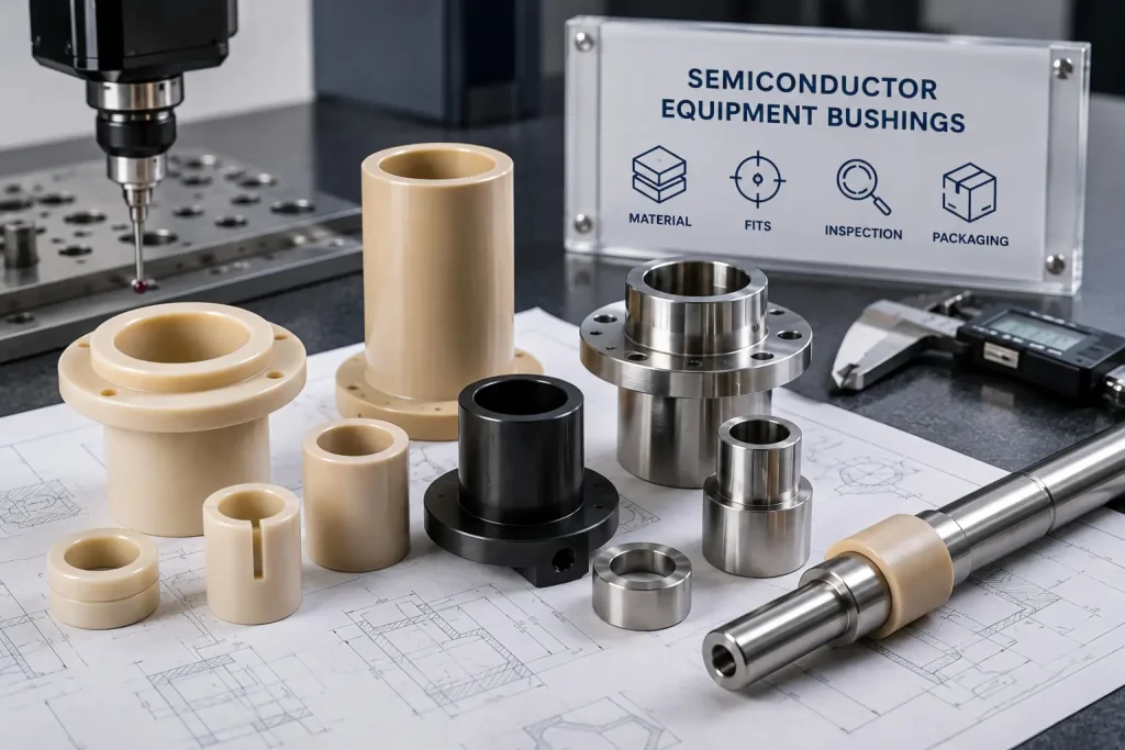
Bushings used in semiconductor equipment may provide alignment, electrical isolation, wear control, thermal separation, shaft guidance, spacing, or protection between mating components.
Although many bushings appear geometrically simple, their performance can depend on several connected requirements:
- Bore and outside-diameter relationship
- Clearance, transition, or interference fit
- Wall thickness
- Flange position
- Material grade
- Temperature range
- Chemical exposure
- Vacuum requirements
- Wear and friction
- Electrical insulation
- Particle and residue limits
- Cleaning and packaging
CNC machining can produce accurate bores, outside diameters, shoulders, flanges, grooves, slots, and mounting features. However, machining accuracy alone does not make a component suitable for every semiconductor, cleanroom, vacuum, plasma, or wafer-handling environment.
The drawing, material specification, operating conditions, cleaning requirements, inspection plan, and packaging instructions must be reviewed together.
Quick Answer
A semiconductor equipment bushing project should normally confirm:
- The bushing’s mechanical function
- The mating shaft and housing materials
- Required fit and assembly method
- Operating and assembly temperatures
- Vacuum or atmospheric service
- Chemical and plasma exposure
- Electrical or thermal insulation requirements
- Sliding, static, or intermittent movement
- Permitted lubricants and processing aids
- Particle, residue, and cleanliness requirements
- Inspection condition
- Packaging and handling requirements
The term semiconductor bushing is not a complete technical specification.
A PEEK alignment sleeve, a polyimide wear bushing, a stainless locating sleeve, and an anodized aluminum spacer may all be used in semiconductor-related equipment, but they require different machining, fitting, cleaning, inspection, and qualification routes.
What Is a Semiconductor Equipment Bushing?
A bushing is generally a cylindrical or flanged component installed between two mating parts.
Depending on the equipment, it may function as:
- A shaft guide
- A replaceable wear surface
- A locating sleeve
- A bearing surface
- A spacer
- An electrical insulator
- A thermal break
- A protective insert
- A press-fit liner
- A connector or feedthrough support
Possible applications include equipment for:
- Wafer handling
- Inspection fixtures
- Motion stages
- Vacuum hardware
- Chemical processing
- Wet benches
- Test equipment
- Packaging and back-end processes
- Automation and robotic mechanisms
The exact process environment matters. A bushing used in a dry inspection fixture does not automatically need the same material or cleaning route as one installed near vacuum, plasma, corrosive chemicals, or a wafer-contact surface.
What CNC Machining Can and Cannot Guarantee
CNC machining can help control:
- Bore diameter
- Outside diameter
- Bore-to-OD concentricity
- Wall-thickness variation
- Flange thickness
- Shoulder position
- Face squareness
- Groove and slot position
- Mounting-hole pattern
- Lead-in chamfers
- Edge and burr condition
- Surface roughness where specified
CNC machining alone cannot certify:
- Cleanroom compatibility
- Zero particle generation
- Zero contamination
- Ultra-high-vacuum compatibility
- A fixed outgassing limit
- Plasma resistance
- Chemical compatibility
- Wafer-contact approval
- Electrical performance
- Long-term dimensional stability
- A complete assembly fit at every temperature
These requirements depend on the exact material grade, manufacturing history, cleaning method, assembly, environment, qualification procedure, and applicable customer specification.
Bushings, Sleeves, Spacers, and Insulating Inserts
These terms are sometimes used interchangeably, but their functions may differ.
Bushing
A bushing normally guides, supports, separates, or protects a mating shaft or cylindrical feature.
It may be:
- Pressed into a housing
- Installed with clearance
- Retained by a flange
- Bonded or mechanically locked
- Replaceable after wear
Sleeve
A sleeve may provide alignment, protection, spacing, insulation, or a controlled cylindrical interface.
Not every sleeve is a wear component.
Spacer
A spacer mainly establishes axial or radial separation.
Its most important requirements may be:
- Length
- Parallelism
- Flatness
- Compression behavior
- Electrical isolation
Insulating Insert
An insulating insert separates conductive components or controls heat transfer.
Its performance may depend on:
- Dielectric requirements
- Temperature
- Wall thickness
- Creep
- Chemical exposure
- Assembly stress
The drawing should define the actual function rather than relying only on the part name.
Material Selection by Equipment Function
There is no universal best material for semiconductor-related bushings.
A material should be selected according to:
- Load
- Wear
- Friction
- Temperature
- Thermal expansion
- Electrical behavior
- Chemical exposure
- Vacuum level
- Cleaning process
- Required stiffness
- Assembly method
- Part life
- Cost
PEEK Bushings
PEEK may be considered where the design requires a combination of:
- Electrical insulation
- Chemical resistance
- Low moisture absorption
- Useful mechanical strength
- Machinability
- Temperature resistance
- Lower weight than metal
Unfilled, glass-filled, carbon-filled, and wear-modified PEEK grades do not behave identically.
Fillers can change:
- Stiffness
- Thermal expansion
- Wear
- Friction
- Electrical behavior
- Machining tool wear
- Surface appearance
- Directional properties
Victrex data show that PEEK grade and filler system materially affect thermal expansion and dimensional behavior. Material-property values can also depend on geometry, processing history, and direction. The exact grade must therefore be written on the drawing or purchase specification.
Do not specify only:
Natural PEEK
when the application actually requires a particular resin family, filler, stock form, certification, or tested property.
Polyimide and High-Temperature Polymer Bushings
Polyimide materials such as selected Vespel grades may be considered for:
- High-temperature components
- Low-friction interfaces
- Wear parts
- Bushings
- Washers
- Insulating components
- Selected wafer-handling or chip-testing equipment
DuPont identifies dimensional stability, wear behavior, and semiconductor back-end applications among the uses of selected Vespel materials. Different grades are formulated for different combinations of friction, wear, temperature, vacuum, strength, and chemical exposure.
The brand name alone is not enough.
The specification should identify:
- Exact grade
- Shape or manufacturing form
- Filler system
- Required properties
- Temperature
- Chemical environment
- Wear condition
- Vacuum or cleanliness requirement
Other high-temperature polymers, including selected PAI materials, also require grade-specific review. A filled wear grade should not be substituted for an unfilled insulating grade without approval.
Stainless Steel Bushings
Stainless steel may be suitable where the project needs:
- Higher stiffness than a polymer
- Stable threads and shoulders
- Wear resistance
- Corrosion resistance
- Repeatable press fits
- Ground or machined bearing surfaces
Possible grades include 303, 304, 316L, 17-4 PH, and other stainless alloys, but they are not interchangeable.
The selection should consider:
- Corrosion environment
- Hardness
- Magnetic requirements
- Weldability
- Passivation
- Galling
- Wear pairing
- Final heat-treatment condition
A stainless bushing may still require electrical isolation, lubricant control, passivation, special cleaning, or protection from dissimilar-metal contact.
Aluminum Bushings and Spacers
Aluminum may suit:
- Lightweight locating sleeves
- Equipment spacers
- Structural inserts
- Larger low-load bushings
- Prototype assemblies
- Components integrated with aluminum frames
Anodizing may provide selected surface protection, electrical behavior, color, or wear resistance.
However, anodizing can affect:
- Bore diameter
- Outside diameter
- Press-fit interference
- Sliding clearance
- Thread fit
- Electrical contact
- Datum surfaces
The drawing should define:
- Alloy and temper
- Anodizing type
- Coating thickness
- Masked surfaces
- Dimensions that apply after treatment
- Electrical-contact areas
- Post-finish inspection
Aluminum should not be selected for a chemical or plasma environment solely because it is easy to machine.
Ceramic Bushings Require a Different Manufacturing Review
Technical ceramics may be used where the application requires:
- Electrical insulation
- High stiffness
- Temperature resistance
- Chemical resistance
- Low wear
- Low thermal conductivity
Alumina, zirconia, quartz, silicon carbide, and other ceramic materials do not follow the same machining route as PEEK, aluminum, or stainless steel.
Depending on the ceramic and material condition, the process may require:
- Green machining
- Sintering allowance
- Diamond grinding
- Lapping
- Specialized edge control
- Dedicated inspection
A conventional CNC metal-machining quotation should not automatically be applied to a finished technical ceramic component.
Thermal Expansion and Dimensional Stability
Polymers generally respond to temperature differently from metal shafts and housings.
A bushing that fits correctly during room-temperature inspection may change clearance when:
- The assembly heats during operation
- The equipment is baked
- The part is cooled
- The polymer absorbs moisture
- A press fit changes the bore
- The part remains under load for an extended period
The review should consider the complete material pair:
- Polymer bushing in an aluminum housing
- Polymer bushing around a stainless shaft
- Stainless sleeve in an aluminum plate
- Filled polymer fitted to a ceramic component
Unfilled and filled PEEK grades can have substantially different coefficients of thermal expansion. Filled grades may provide lower expansion, but can also introduce anisotropy, different wear behavior, and greater tool abrasiveness.
The drawing should identify the temperature at which the fit and dimensions must function.
Clearance, Transition, and Press Fits
A bushing fit should be selected from its function, not from one universal interference value.
Clearance Fit
A clearance fit may be appropriate where the bushing must:
- Slide into position
- Be removable
- Allow thermal movement
- Rotate around a shaft
- Avoid distorting a soft polymer
The maximum and minimum operating clearance should be evaluated at the relevant temperatures.
Transition Fit
A transition fit may provide controlled location with limited installation force.
It can be useful when:
- Alignment matters
- Removal may still be required
- Excessive compression would change the bore
Press Fit
A press fit may retain a bushing without a separate fastener.
For polymer bushings, pressing the OD into a housing can reduce the finished ID. The amount depends on:
- OD interference
- Wall thickness
- Material stiffness
- Housing material
- Lead-in geometry
- Installation temperature
- Time under compression
- Material creep
- Surface finish
The functional bore may need to be verified after installation rather than only before assembly.
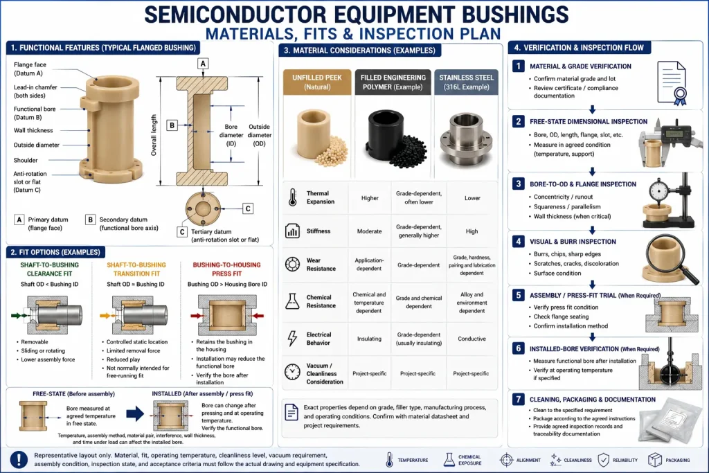
Do not specify an extremely tight free-state bore tolerance while ignoring the change caused by the press fit.
Bore Concentricity, Wall Thickness, and Datum Planning
A cylindrical bushing may require several related controls:
- Bore diameter
- Outside diameter
- Bore-to-OD concentricity or runout
- Wall-thickness variation
- Flange-face squareness
- Flange thickness
- Shoulder position
- Slot orientation
- Mounting-hole position
A representative datum structure could use:
- Datum A: Primary flange face
- Datum B: Functional bore or outside diameter
- Datum C: Slot, flat, hole, or clocking feature
The correct datum structure depends on how the bushing is assembled and located.
A blanket ±0.01 mm tolerance does not define:
- Coaxiality
- Circular runout
- Cylindricity
- Perpendicularity
- Profile
- Functional fit
For fit, datum, runout, GD&T, and inspection planning, review our CNC machining tolerances guide.
Machining Thin-Wall Polymer Bushings
Thin polymer sleeves can deform during:
- Chucking
- Collet clamping
- Boring
- Parting
- Deburring
- Measurement
- Storage
The machining process may need:
- Sharp tools
- Controlled clamping pressure
- Short tool reach
- Stable material support
- Light finishing cuts
- Heat control
- Clean chip evacuation
- Appropriate parting support
- Free-state inspection
A mandrel or internal support may help some geometries, but it is not a universal solution. The support itself can stretch or distort a thin polymer bushing.
The final inspection should occur after the part is released from the fixture and allowed to reach the agreed measurement condition.
Burrs, Sharp Edges, and Particle-Trap Risks
Small burrs and damaged edges can affect:
- Assembly
- Particle generation
- Shaft wear
- Seal damage
- Fit
- Handling safety
- Cleaning effectiveness
Potential problem areas include:
- Bore entries
- Cross holes
- Slots
- Flange edges
- Internal shoulders
- Thread starts
- Parting locations
The drawing should identify which edges require:
- A defined chamfer
- A controlled radius
- A simple edge break
- A sharp functional edge
- No secondary hand finishing
Over-aggressive manual deburring may change a fit or create loose polymer fragments.
Cleaning Requirements Must Be Specified
Clean for semiconductor use is not a complete cleaning instruction.
The purchase requirement should define:
- Prohibited machining fluids or substances
- Cleaning chemistry
- Rinse-water requirements
- Ultrasonic cleaning permission
- Maximum cleaning temperature
- Drying method
- Residue limits
- Particle requirements
- Visual-inspection method
- Gloves and handling controls
- Packaging method
- Documentation
Some polymers, coatings, adhesives, and filled materials may not be compatible with every solvent, ultrasonic process, or drying temperature.
CNC machining followed by ordinary degreasing does not automatically establish cleanroom or wafer-contact suitability.
Rapid Efficient can coordinate cleaning and packaging requirements when they are defined before quotation, but the required cleanliness level and validation method must come from the project specification.
Vacuum and Outgassing Requirements
Outgassing is the release of volatile material under heat or reduced pressure.
For vacuum-sensitive equipment, the buyer may need to define:
- Operating pressure
- Bake temperature
- Maximum service temperature
- Permitted materials
- TML or CVCM limits
- Required test method
- Lot or batch qualification
- Cleaning
- Packaging
- Storage
ASTM E595 is a screening test that measures total mass loss and collected volatile condensable materials under a defined vacuum and temperature exposure. NASA also maintains a database of results generated using this type of testing. These resources can help assess material candidates, but they do not create a universal “semiconductor-approved” classification.
A material trade name or supplier brochure should not replace the actual project qualification requirement.
Machining oils, absorbed moisture, cleaning residues, packaging, adhesives, and assembly materials can also affect the final vacuum system.
Dimensional and Visual Inspection
The inspection plan should focus on functional features.
Possible dimensional checks include:
- Bore diameter
- Outside diameter
- Flange diameter
- Flange thickness
- Overall length
- Wall-thickness variation
- Bore-to-OD runout
- Face squareness
- Groove dimensions
- Slot and hole position
- Thread fit
- Press-fit condition after assembly
Possible inspection equipment includes:
- Micrometer
- Bore gauge
- Pin or plug gauge
- Height gauge
- CMM
- Optical measurement
- Roundness equipment
- Dedicated functional fixture
Soft or thin polymer components can move under probe or gauge force. The measurement method, support condition, temperature, and stabilization time should therefore be agreed when tolerances are sensitive.
Visual inspection may check:
- Burrs
- Chips
- Scratches
- Cracks
- Embedded contamination
- Damaged threads
- Discoloration
- Handling marks
- Packaging cleanliness
For inspection methods and reporting options, review our quality assurance for CNC machined parts.
Packaging and Handling
Packaging requirements depend on the next process.
Possible instructions include:
- Individual bags
- Trays
- Protective caps
- No metal-to-metal contact
- Lint-controlled handling
- Double bagging
- Clean labels
- Lot separation
- Desiccant
- Specific packaging materials
These should only be used when the project requires them.
Double bagging or clean packaging does not by itself prove that a part meets a cleanroom or contamination standard.
The customer and supplier should agree:
- Final cleaning location
- Packaging environment
- Packaging material
- Bag count
- Label information
- Opening procedure
- Storage limits
Information Required Before Quotation
Provide the following information for a semiconductor equipment bushing project:
- 3D CAD model
- 2D drawing
- Bushing function
- Mating shaft and housing dimensions
- Material and exact grade
- Operating temperature
- Assembly temperature
- Vacuum level, when applicable
- Chemical or plasma exposure
- Sliding or static condition
- Fit requirement
- Installation method
- Electrical or thermal requirements
- Critical dimensions and GD&T
- Surface-finish requirements
- Cleaning specification
- Prohibited substances
- Packaging requirements
- Certificate and report requirements
- Prototype and production quantity
Do not request semiconductor-grade machining without defining what the phrase means for the actual equipment and process.
FAQ
What Is the Best Material for a Semiconductor Equipment Bushing?
There is no universal best material.
PEEK may suit selected insulating and chemical-resistant components. Polyimide may be considered for high-temperature, wear, and selected semiconductor equipment applications. Stainless steel offers greater stiffness and stable mechanical features. Aluminum may be suitable for lightweight structural sleeves and spacers.
The exact grade and environment must be reviewed.
Is PEEK Automatically Suitable for Vacuum Use?
No.
PEEK is used in selected vacuum-related applications, but suitability depends on the exact grade, temperature, cleaning, outgassing requirement, processing history, and qualification method.
Filled and unfilled grades may behave differently.
Can a PEEK Bushing Hold Very Tight Tolerances?
Selected features can be machined accurately, but the achievable result depends on:
- Size
- Wall thickness
- Material grade
- Stock condition
- Temperature
- Clamping
- Measurement force
- Press-fit deformation
- Stabilization
- Final assembly
A universal ±0.002 mm capability should not be promised for all PEEK bushings.
Should a Polymer Bushing Be Measured Before or After Pressing?
Both may be required.
Free-state inspection verifies the machined part. Post-installation inspection confirms whether the bore and functional fit changed after pressing.
The drawing should define the acceptance condition.
Does a Smooth Surface Prevent Particle Generation?
Not by itself.
Particle behavior can also be affected by burrs, wear, material choice, friction, assembly, cleaning residues, handling, and the operating environment.
Can Ultrasonic Cleaning Be Used for Every Bushing?
No.
Ultrasonic cleaning must be compatible with the material, geometry, fluid, temperature, surface condition, and customer process. Thin parts, coatings, fillers, and trapped cavities may require a different route.
Does ASTM E595 Certify a Material for Semiconductor Equipment?
No.
ASTM E595 is a defined vacuum-outgassing screening method. A project may reference it, but acceptance limits and relevance must be established by the equipment or customer specification.
What Inspection Report Can Be Provided?
The required report can be agreed before quotation and may include:
- Dimensional results
- Material certification
- Thread or gauge results
- CMM results
- Surface-finish results
- Visual-inspection records
- Cleaning or packaging documentation
The report scope depends on the drawing and purchase requirements.
Review Your Semiconductor Equipment Bushing Before Machining
Send the complete drawing package together with the material grade, fit, temperature, vacuum or chemical environment, cleanliness requirements, packaging instructions, quantity, and inspection needs.
Rapid Efficient can review:
- Bore and OD relationships
- Fit and assembly risks
- Thin-wall stability
- Tool access
- Material alternatives
- Thermal-expansion risks
- Burr-sensitive areas
- Cleaning and packaging requirements
- Inspection priorities
- Prototype and low-volume production routes
For other semiconductor equipment-related fixtures, housings, adapters, plates, and structural components, review our semiconductor equipment manufacturing capabilities.
For custom bushings, sleeves, spacers, and close-tolerance components, review our precision machining services.