An end mill can show a small indicator reading close to the holder and a larger reading farther out. Replacing the cutter may leave the problem unchanged. Moving the indicator may change the reported value even though nothing in the assembly has moved.
Tool runout describes variation in the position of a tool surface or cutting edge as the assembly rotates about its actual axis. A useful check identifies the measuring surface, distance from a fixed reference, and assembly condition. Those details turn a number into evidence you can use.
This guide focuses on rotating tools used for milling and hole machining. Start with a repeatable measurement, isolate the source, and then check whether the finished feature improves.
A Runout Number Needs a Measuring Position
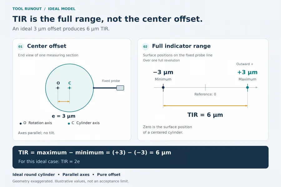
For a radial indicator check at one axial location, total indicator reading, or TIR, is the highest reading minus the lowest over one complete revolution.
TIR = maximum reading − minimum reading
For example, readings from −0.002 mm to +0.004 mm give:
TIR = 0.004 − (−0.002) = 0.006 mm = 6 µm
This is an illustrative calculation, not an acceptable runout limit.
The reading includes the behavior of the measured surface and the rotating assembly. Surface form, bend, mounting error, and spindle motion can contribute. A tool-shank reading therefore does not isolate spindle error. Lion Precision’s shaft-runout explanation describes these contributions and the peak-to-peak measurement.
For an ideal round cylinder whose axis is parallel to, but offset from, the rotation axis, TIR equals twice the center offset. In that limited model, 6 µm TIR corresponds to 3 µm eccentricity. A real tool reading should not be halved automatically to report a centerline error.
Also keep total indicator reading separate from the GD&T control called total runout. Measuring one circle on a tool shank does not inspect an entire finished-part surface relative to its drawing datum. The concentricity and runout guide covers that different inspection task.
The Shank and the Cutting Edge Can Give Different Results
A smooth cylindrical shank gives an accessible measuring surface. It does not prove that every cutting edge reaches the same radius. Flute grinding, edge damage, or built-up material can change the cutting envelope independently of the shank reading.
Choose the measuring position to answer a specific question:
| Measuring position | What the check can help assess | What it does not establish |
|---|---|---|
| Verified spindle test bar at the maker’s specified locations | Behavior of the spindle interface and reference bar as assembled | Cutter geometry or the condition of a separate production holder |
| Precision test pin held in the production holder | Holder, collet, and seating behavior with that pin | Runout of the actual cutting edges |
| Smooth tool shank close to the holder | Local shank runout in the current assembly | The reading farther along the tool |
| A second suitable shank location farther out | How the reading changes with measuring distance | A unique diagnosis of tilt, bend, or offset |
| Individual cutting edges at a defined cutting height | Differences in the edge positions that generate the cut | Behavior at another cutting height or under cutting load |
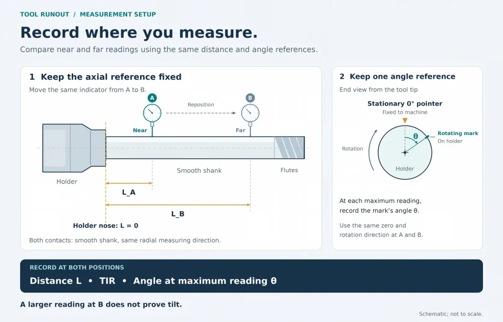
Record the measuring distance from the same reference each time, such as the holder nose or a defined gauge line.
Use a rigid indicator setup and the contact geometry specified for the instrument. Follow the machine builder’s approved manual-rotation procedure with powered spindle rotation disabled. Check that repeated revolutions give a consistent result before comparing components.
Do not let a contact tip drop into flute gaps and treat the resulting movement as radial TIR. Small or delicate cutting edges may need an optical presetter or another suitable noncontact method. The method must resolve the feature you intend to assess without damaging it or causing significant deflection.
Keep radial and axial checks separate
Radial runout concerns variation perpendicular to the rotation axis. An axial cutting-edge check compares edge positions along that axis, such as insert-height differences on a face mill.
A radial check on the cutter body cannot establish that all face-milling inserts cut at the same height. If one insert leaves a dominant track, review the insert seats and axial edge positions. The face milling guide explains how these differences affect the finished surface.
Separate Spindle, Holder, and Cutter Errors
Replacing the cutter, collet, and holder together may improve a result, but it leaves the source uncertain. Use a sequence that changes one relevant part of the assembly at a time.
Establish a reference before changing parts
Inspect the measuring setup first. A moving indicator base, dirty test surface, or excessive contact force can make a sound assembly appear faulty.
Then inspect the interfaces: spindle taper, holder contact surfaces, collet bore, nut, and tool shank as applicable. Follow the holder maker’s cleaning, lubrication, gripping-length, and tightening instructions. Different holder systems need different assembly methods. More tightening torque is not a general cure for runout.
For an ER nut with an eccentric extractor ring, snap the collet into the nut before fitting the assembly to the holder, as shown in REGO-FIX’s ER assembly instructions. Follow the maker’s insertion and tightening instructions. Incorrect assembly can increase runout or damage the clamping parts.
Use a verified spindle test bar and the machine maker’s specified measuring positions when the spindle interface is in question. A poor result starts an investigation; it does not prove that the spindle bearings need replacement.
Compare near and far readings carefully
A larger reading farther from the holder can be consistent with a tilted assembly. A bent bar or a combination of errors can produce a similar result.
Record both TIR and the angular position of the high point at each measuring location, using the same angular reference mark. Comparing only the two TIR values loses information about error direction and surface shape.
This also explains why a low reading at one location should not be used to judge the full tool length.
Use controlled assembly comparisons
Once the reference check is repeatable, use comparisons such as these:
| Controlled comparison | Observation worth recording | Follow-up |
|---|---|---|
| Remove and reseat the same assembly using the same method | TIR or high-point position changes between installations | Check seating cleanliness, retention, assembly method, and measurement repeatability |
| Measure the same verified test pin in two compatible holders | The difference repeats with one holder assembly | Investigate that holder and its clamping components |
| Compare a verified test pin and the actual tool with the same nominal shank diameter in the same holder | The pin is acceptable but the tool shank is not | Check the tool shank, grip compatibility, insertion depth, and assembly consistency |
| Compare shank readings with cutting-edge measurements | The shank is acceptable but cutting-edge positions differ | Inspect edge geometry, damage, built-up material, or insert seating |
Keep the measuring position, projection, reference, and measurement method consistent across each comparison.
Where the holder design permits it, a controlled change in tool orientation can provide more evidence. An improvement may reflect partial cancellation between errors. It does not prove that the underlying components are individually accurate.
Do not subtract two TIR values and assign the difference to one component. The direction of each error matters, so the assembled result is not a simple sum of independent readings.
Why One Cutting Edge Carries More Load
The programmed feed per tooth is a nominal value. It does not mean every edge removes the same amount of material when their cutting radii differ.
An edge that projects farther can remove more stock and leave less for a following edge. This can produce uneven wear or overload one edge. The effect depends on engagement, feed, tool geometry, and deflection.
This is especially relevant when the intended chip thickness is small. A runout value that looks small beside the cutter diameter may still be important compared with the material each edge is meant to remove. Reducing feed alone does not correct unequal cutting radii.
Runout can contribute to varying cutting forces, but it does not prove that regenerative chatter is present. Use the machining chatter guide when the problem also involves vibration, changing engagement, or workpiece flexibility.
Hole oversize is not a direct TIR conversion
A rotating tool’s cutting envelope can affect hole size. However, drill guidance, edge condition, material response, and deflection also affect the result. Measured shank TIR cannot be added directly to the nominal drill diameter to predict every finished hole.
Treat an oversized hole as a feature to investigate. Compare tool measurements with bore diameter, roundness, and any change along the hole depth. A single diameter reading cannot identify the complete cause.
Likewise, a cutter compensation change may bring a milled dimension closer to target while leaving unequal edge loading in place. Geometry correction in the program does not repair the tool assembly.
Set the Limit for the Actual Tool and Operation
There is no single runout limit that suits every end mill, drill, reamer, and machining operation.
Start with the tool and holder suppliers’ requirements, including the measurement location and projection used for the specification. A holder rating measured with a test bar does not automatically describe the cutting edge of a longer production assembly.
Then consider the actual operation: cutter diameter, edge geometry, intended chip thickness, reach, material, and the feature being produced. A limit chosen for general roughing may be unsuitable for a small finishing tool or a precision reamer.
If the current assembly cannot consistently meet the required runout limit, compare suitable precision collet, shrink-fit, or hydraulic holders. Check each specification at its stated measuring length, then verify the assembled tool at the working projection. The holder type alone does not guarantee the result.
Three requirements need separate treatment:
- Tool-assembly limit: what must be controlled at a stated measuring location and assembly condition.
- Measurement capability: whether the instrument and setup can distinguish an acceptable result from an unacceptable one.
- Part acceptance: whether the finished feature meets its size, form, location, and surface requirements.
A low tool-runout reading supports process control. It does not certify the part. The CNC machining tolerances guide explains how manufacturing and inspection requirements fit into the wider tolerance budget.
If runout evidence is required from a supplier, ask for the assembled tool, measuring surface, reference distance, method, and result together. A number without these conditions is difficult to compare with another supplier’s report.
Check the Assembly Again After a Tool Change
A result belongs to the assembly that was measured. Removing the tool, changing a collet, or replacing an insert creates a new condition. Define which changes trigger a repeat check, especially for tools that control critical features.
Keep a short setup record: tool and holder identification, projection, measuring locations, readings, and the change made. If orientation is deliberately controlled, record it as well. This helps the next setup reproduce the intended condition.
A slow check does not prove performance at cutting speed
Balance, speed-dependent spindle motion, thermal changes, and cutting-force deflection require separate consideration.
When a problem appears only at operating speed, use an appropriate noncontact measurement system or the machine builder’s diagnostic process. Do not attempt the same check by leaving a contact indicator against a tool running at machining speed.
After correcting the assembly, repeat a comparable machining operation and inspect the affected feature. Compare edge wear, dimensions, and surface condition. If the static reading improves but the part problem remains, review the other cutting and setup conditions.
For a narrow slot, small bore, or long-reach wall that is difficult to hold within tolerance, share the marked feature and the tool information together. Useful details include cutter diameter, projection, holder type, measuring location, TIR, and the observed size or surface problem.
Use our CNC milling services page to request a part-manufacturing review. RapidEfficient can review feature access, tooling options, and inspection requirements before quotation. The review should establish which tool conditions matter to that feature and how the finished result will be checked.