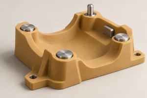
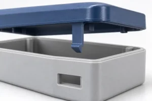
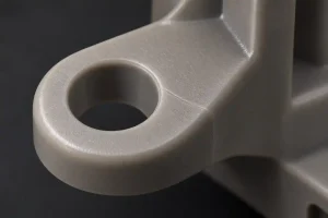
A clear cover has to do more than survive machining. It may need to show small display characters, stay readable after repeated cleaning, or resist an accidental impact. Those jobs do not lead to the same material choice.
When choosing between acrylic and polycarbonate, start with the finished part’s main requirement. Acrylic, also called PMMA, is often a strong candidate for clear display parts and polished edges. Polycarbonate, or PC, is usually the stronger candidate when impact resistance matters more. Neither choice removes the need to check the grade, surface condition, mounting, and chemical exposure.
The useful comparison is between two complete options: material, geometry, finish, and service conditions. A polished acrylic cover and an untreated polycarbonate cover are not equivalent specifications.
| Clear-part requirement | Starting option to evaluate | What could change the choice |
|---|---|---|
| Display cover with visible edges and limited impact exposure | Clear PMMA with defined face and edge finishes | Frequent knocks, mounting stress, or an incompatible cleaner |
| Inspection window exposed to accidental impact | A suitable clear PC grade | Required protection level, panel support, abrasion, and chemical contact |
| Window that must resist impact and frequent wiping | Abrasion-resistant PC, if the coating suits the part | Coating on the wrong face, machining through it, or an unsupported cleaning process |
| Transparent housing with milled pockets and viewing walls | Compare the complete PMMA and PC machining routes | Access for finishing, stress near holes, and whether the final viewing path stays usable |
These are starting points, not approvals for a particular assembly. For materials outside this comparison, see our best plastics for CNC machining guide.
Display Covers: Clear Faces and Finished Edges
Acrylic often makes sense when appearance is the main job and impact exposure is limited. Standard uncoated PMMA generally has better scratch resistance than standard uncoated PC. PLEXIGLAS describes the surface-hardness comparison in its scratch-resistance guidance. Surface hardness is not proof that acrylic will withstand a harder impact.
For a display cover, separate three questions:
- How much light must pass through the part?
- How clearly must the user see the object or text behind it?
- Which faces and edges must look good when viewed from outside?
Light transmission, haze, and image distortion describe different aspects of viewing quality. Transmission is the share of incoming light that passes through the material. Haze is wide-angle light scattering that reduces contrast and creates a cloudy appearance. This scattering can come from the surface or from within the material. Distortion changes the apparent shape, position, or size of what the viewer sees. A transmission value alone does not establish viewing quality.
Compare optical data at the relevant thickness, color, coating, and test conditions. Do not use a thin, flat sheet’s published value as acceptance evidence for a thick machined housing.
Keep the viewing face separate from the edge finish
For a flat cover cut from suitable sheet, it may be possible to keep the supplied faces and machine only the outline and holes. That is a different job from milling a broad viewing face and then restoring its clarity.
PMMA edges can be finished to a clear appearance, but a glossy edge does not prove that a viewing face is flat or free from distortion. Local polishing also removes material. A finish that improves appearance can change an edge, a sealing land, or a close-fitting feature.
For PC, vapor polishing can improve surface clarity, but it may also round small edges. Any associated annealing can change dimensions as residual stresses relax. Agree on the areas allowed to receive finishing, then inspect critical dimensions, sealing surfaces, and viewing quality after the complete process.
Specify where a clear edge matters and where a normal machined edge is acceptable. Our acrylic CNC machining guide covers the machining and polishing risks in more detail.
If users must read a display through the part, assess it over the actual display or a defined viewing target. Agree on lighting, distance, angle, and the area being judged. A sample can help define cosmetic expectations, but safety or precision optical requirements need their own acceptance criteria.
For displays that use polarized light, also check birefringence: differences in refractive index that can change how polarized light passes through a cover. Residual stress and molecular orientation can cause this effect in both PC and PMMA. Color fringes or uneven brightness can appear when the cover sits between a polarized light source and another polarizer, such as an LCD viewed through polarized sunglasses.
Low-stress optical-grade cast PMMA is an option to evaluate, but it is not a guarantee that the finished part will remain free of stress. Machining and mounting can introduce new stress. Test the finished cover with the intended display, viewing angles, and eyewear.
Inspection Windows: Impact and Repeated Cleaning
Polycarbonate is usually the first material to evaluate when a clear part must resist accidental impact. However, impact resistance, stiffness, and surface hardness are separate properties.
A PC window may resist fracture yet deflect too far for the available clearance. A window that survives a knock may still become difficult to see through after repeated abrasive cleaning. Thickness, unsupported span, frame support, and the required viewing quality all remain part of the decision.
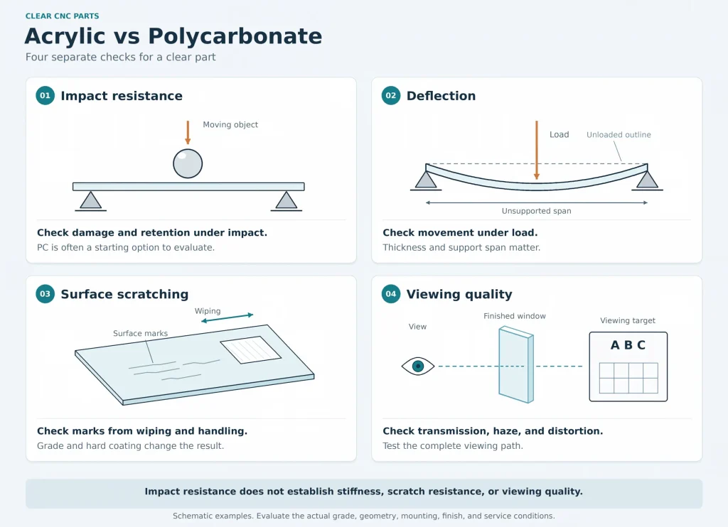
Do not reduce the comparison to a universal claim that one plastic is a fixed number of times stronger. Impact results depend on the grade, specimen, notch, temperature, and test method. They do not directly specify a safe panel thickness.
A hard coating changes the surface comparison
Abrasion-resistant PC can combine impact resistance with a more durable viewing surface. That does not make every PC sheet scratch-resistant or compatible with every cleaner.
For a coated part, identify:
- Which supplied faces carry the coating.
- Which face will receive wiping, splashes, or outdoor exposure.
- Whether machining removes the coating from a required area.
- Whether the selected coating permits the planned forming or finishing operation.
Drilling and milling expose new surfaces. A hard coating on the original sheet face does not automatically cover a bore wall, a pocket floor, or a cut edge. Those areas retain the properties of the base material, but they do not inherit the face coating’s protection. Confirm whether exposed areas need additional protection and whether a suitable post-machining process is available.
If the window is intended to protect people from ejected parts or tool fragments, material selection is only one step. The complete guard, including thickness, frame, fasteners, openings, and exposure conditions, needs validation against the applicable safety requirements. A generic PC property sheet is not that validation.
Machined Clear Housings: Pockets, Holes, and Assembly
A housing machined from clear stock can have a transparent outer face and a milled inner wall. The observer looks through both. Keeping the outer face clear does not compensate for tool marks or distortion on the inner surface.
Before choosing PMMA or PC, trace the viewing path through the CAD model. Then identify every surface that the path crosses.
| Surface in the finished part | What the stock specification tells you | What still needs to be decided |
|---|---|---|
| Supplied sheet face left intact | Its original surface and any specified coating | Handling protection, viewing direction, and permitted marks |
| Milled wall or pocket floor in the viewing path | The base polymer and grade | Required clarity, finishing access, and the effect of finishing on geometry |
| Cut edge, drilled hole, or threaded feature | The base material, but not coating coverage on the new surface | Burr control, local stress, contact chemicals, and any required protection |
| Sealing land or locating face beside a clear area | Base-material properties, not the final feature size or form | Final size and form after the agreed finishing operations |
Mark the viewing surfaces separately from cosmetic edges and functional contact faces.
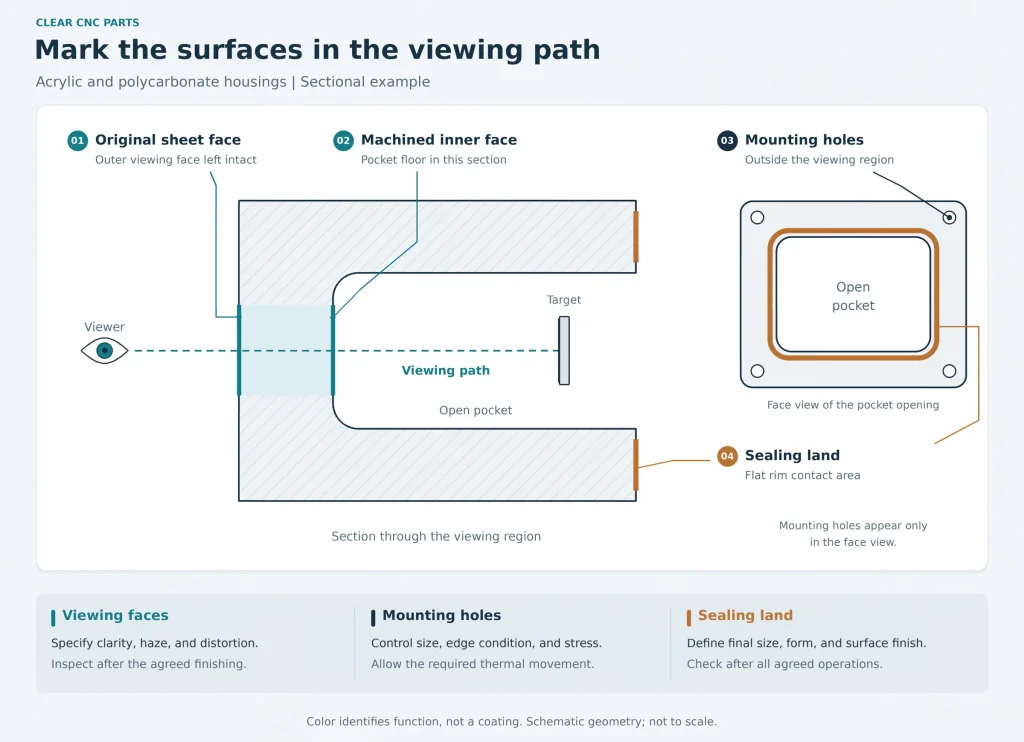
A useful instruction can allow normal machining marks outside the viewing zone while setting stricter limits inside it. Requiring every face of a deep housing to be polished may add cost without improving the view that actually matters.
More impact resistance does not make holes risk-free
PMMA’s lower toughness deserves attention around thin ligaments, sharp internal corners, and mounting holes. PC offers greater impact tolerance, but it can still develop environmental stress cracking. This means chemical exposure and tensile stress act together to cause cracking or fine surface crazing.
The stressed area may come from the stock, machining, finishing, or assembly. A fastener that pulls a warped cover flat can add stress even when the hole diameter is correct. A cleaner or adhesive that appears harmless on an unstressed sample may behave differently around a loaded hole.
For either material, review the load path through the mounting features. Avoid conical screw heads bearing directly on the plastic. Prefer flat-bearing fasteners with suitable washers, and use counterbores only where enough material remains beneath them. PLASKOLITE’s TUFFAK fabrication guide explains how conical heads can create undesirable local stresses.
Provide clearance or slots where differential thermal expansion requires movement. Control clamp load so the joint does not lock that movement. A correctly sized shoulder or spacer can limit compression; a soft washer alone does not set a reliable limit. Check washer and gasket compatibility with the selected plastic grade.
Threaded inserts, through-bolts, and direct plastic threads create different local loads. Choose the joint with the material and geometry, rather than treating an insert as an automatic cure for cracking. The polycarbonate machining guide explains the PC stress-history problem in detail.
Finishing and any specified stress-relief treatment also belong in the dimensional plan. Define acceptance after the agreed operations and under a stated measurement condition. Use the CNC machining tolerances guide to separate size, form, and inspection requirements.
Heat, Sunlight, and Chemicals Can Change the Choice
A material that suits the shape may not suit the service environment. Check the actual conditions before accepting either option.
Heat: compare the loaded part, not one temperature number
Standard PC grades generally offer higher heat resistance than standard PMMA grades. Compare the selected grades under the same test method and load. A material data sheet does not provide a universal working-temperature limit for every housing made from that polymer.
A heat-deflection temperature is measured under a specified test load. It is not a guarantee of long-term dimensional stability at that temperature. ASTM D648’s scope and use guidance explicitly limits using the test data to predict endurance at elevated temperatures. Check the grade’s data together with wall thickness, support, sustained load, and exposure time.
For example, a window under sustained load may slowly deform even below the grade’s published heat-deflection temperature. That movement can affect clearance or seal compression. Check the mounted part under the expected load and temperature for the required service time.
Include local heat sources and the cleaning cycle. A window near a motor or lamp may run hotter than the surrounding air. Neither plastic should be assumed suitable for hot cleaning or steam sterilization simply because it remains clear at room temperature.
Sunlight: name the outdoor grade and the protected side
PMMA is widely used where outdoor clarity matters. For PC, confirm the grade’s outdoor suitability and specified UV protection. Depending on the product, protection may be provided within the material or by a layer on one or both faces. Check any coating’s outdoor suitability for either polymer.
Where protection is provided by a surface layer, the protected face and any material removed during machining matter. A UV-resistant material is also not necessarily a material that passes or blocks the wavelengths needed by a sensor. Check spectral transmission when the light itself performs a measurement or curing function.
Chemicals: include assembly products and cleaning residues
Compare the specific chemical, concentration, temperature, contact time, and stress condition. A broad label such as “chemical-resistant plastic” is not enough. Both PMMA and PC have chemical compatibility limits.
List cleaners, coolants, adhesives, threadlockers, sealants, and gasket materials that may contact the finished part. Use the chosen material manufacturer’s compatibility guidance and evaluate the proposed exposure on a representative finished sample when needed. A test on plain stock does not reproduce a stressed, coated, or polished assembly.
If the required cleaner, temperature, impact duty, or optical function cannot be supported, do not force a PMMA-or-PC choice. Another transparent material, a separate replaceable window, or a revised enclosure design may be more suitable.
Compare the Cost of the Finished Part
Raw sheet price is only part of the comparison. Two quotes can name the same polymer while including very different work.
One may leave the original viewing faces intact. Another may include machining and finishing both faces. One PC quote may use basic stock, while another includes a specified abrasion-resistant grade. Those differences should be visible before comparing unit prices.
For a fair comparison, keep these requirements aligned:
- The area that must remain clear and the view it must provide.
- The final thickness, mounting arrangement, and critical dimensions.
- The selected grade and any face-specific coating.
- The permitted finish on pockets, edges, and non-viewing areas.
- The required checks after finishing, assembly, and relevant exposure.
Consider replacement cost as well. A less expensive cover that meets its cosmetic requirements but needs frequent replacement may not be the lower-cost option in use. Conversely, an expensive coating on a hidden face may add no useful value.
For a material and machining review, send a marked CAD view showing what must be seen through the part. Include the mounting method, impact requirement, operating temperature, cleaning products, and any proposed coating. A photograph of the display, mechanism, or viewing task is often more useful than the instruction “optically clear.”
Share those details through our CNC milling services page. RapidEfficient can review the PMMA and PC options, identify surfaces that need additional finishing, and discuss the machining and inspection scope before quotation.