7075 aluminum is selected for thin-wall CNC parts when higher strength and lower weight are important. However, high material strength does not automatically make a thin-walled component dimensionally stable.
As material is removed, the remaining walls lose stiffness. Residual stress in the stock, cutting force, heat, tool pressure, and clamping force can then cause:
- Wall deflection during cutting
- Chatter and visible tool marks
- Tapered or bowed walls
- Dimensional movement after unclamping
- Flatness changes after machining
- Burrs around thin edges
- Color variation after anodizing
- Fit problems caused by anodic coating growth
A successful process therefore needs more than a rigid CNC machine. Material condition, stock form, machining sequence, fixture support, finishing allowance, inspection state, and anodizing requirements must be reviewed together.
Quick Answer
For a 7075 thin-wall CNC part, the main risk is not whether the cutter can remove the material. The real challenge is whether the component remains within tolerance after material removal, unclamping, stabilization, inspection, and surface treatment.
A practical process usually includes:
- Confirming the correct 7075 temper and stock form
- Selecting stress-relieved plate where appropriate
- Removing material gradually rather than finishing one side immediately
- Keeping temporary support around weak walls
- Leaving controlled stock for semi-finishing and finishing
- Releasing and reclamping the part before final inspection
- Using sharp aluminum-specific tools with short practical reach
- Separating roughing and critical finishing operations
- Inspecting the part in the required free or restrained condition
- Reviewing anodizing allowance, masking, and cosmetic expectations before machining
There is no universal minimum wall thickness or guaranteed tolerance for all 7075 components. A short supported wall and a large unsupported housing may behave very differently even when both have the same nominal thickness.
Why 7075 Thin-Wall Parts Deform
Thin-wall deformation normally comes from several effects acting together.
Loss of Structural Stiffness
The original billet or plate may be rigid before machining. Once large pockets are removed, the remaining walls can bend under relatively small forces.
This can happen during:
- Cutting
- Clamping
- Probing
- Deburring
- Handling
- Inspection
- Surface finishing
A wall may temporarily move away from the cutting tool and spring back after the tool passes. The machine position can be correct while the final wall dimension is not.
Residual Stress in the Stock
Aluminum plate may contain residual stress from rolling, heat treatment, straightening, stretching, and other material-processing steps.
When material is removed unevenly, the original stress balance changes. The remaining part may bow, twist, or open after it is removed from the fixture.
Research on thin-wall milling consistently identifies initial residual stress, machining-induced stress, cutting load, and clamping conditions as major contributors to post-machining deformation.
Machining-Induced Stress
The cutting process can create additional stress near the machined surface.
Its effect depends on:
- Tool sharpness
- Cutting force
- Cutting temperature
- Tool wear
- Toolpath
- Engagement
- Coolant delivery
- Finishing allowance
This is one reason why an aggressive final pass is not always suitable for a weak wall.
Clamping Distortion
A part can measure correctly while it is being forced into position by the fixture.
After the clamps are released, it may:
- Spring outward
- Bow upward
- Twist
- Change pocket width
- Lose parallelism
- Move outside the specified profile or flatness zone
Final acceptance must therefore define whether the part is inspected freely, supported, or restrained in an assembly-equivalent condition.
7075-T6 vs 7075-T651
The temper designation matters when selecting stock for a heavily machined component.
| Material condition | Practical meaning for machining |
|---|---|
| 7075-T6 | Solution heat-treated and artificially aged |
| 7075-T651 | Solution heat-treated, stress-relieved by stretching, and artificially aged |
| 7075-T73 or T7351 | Overaged conditions often selected where stress-corrosion resistance is more important |
| Extruded or bar conditions | Availability and stress-relief designation may differ from plate |
For machined parts produced from plate, 7075-T651 is often considered when dimensional stability matters because the material has been stress-relieved by stretching. It should not be described as completely free of residual stress, and it does not eliminate deformation caused by poor geometry, unbalanced machining, weak fixturing, or cutting heat.
Kaiser lists 7075-T651 as a low-residual-stress plate option, while its 7075 technical data distinguishes the available tempers and product forms.
The drawing and purchase order should identify:
- Alloy
- Temper
- Product form
- Material standard
- Required certification
- Grain-direction requirement, when functionally relevant
Writing only “7075 aluminum” leaves too much room for interpretation.
Define the Inspection State Before Machining
Thin-wall disputes often begin because the drawing defines dimensions but not the condition in which they must be verified.
Before production, confirm:
- Is the part inspected immediately after machining or after stabilization?
- Is it measured in a free state?
- Can it be supported on specified datum points?
- Is a functional checking fixture required?
- Are dimensions required before or after anodizing?
- Does flatness apply to an individual surface or the complete assembly?
- Are cosmetic and dimensional requirements evaluated separately?
- Which features control assembly, sealing, alignment, or bearing fit?
A requirement such as flatness ±0.02 mm should also be corrected. Flatness is normally specified as a total tolerance zone, such as flatness 0.02 mm, rather than as a plus-or-minus dimensional tolerance.
For broader tolerance planning, see our CNC machining tolerances guide.
A Practical Machining Strategy for 7075 Thin Walls
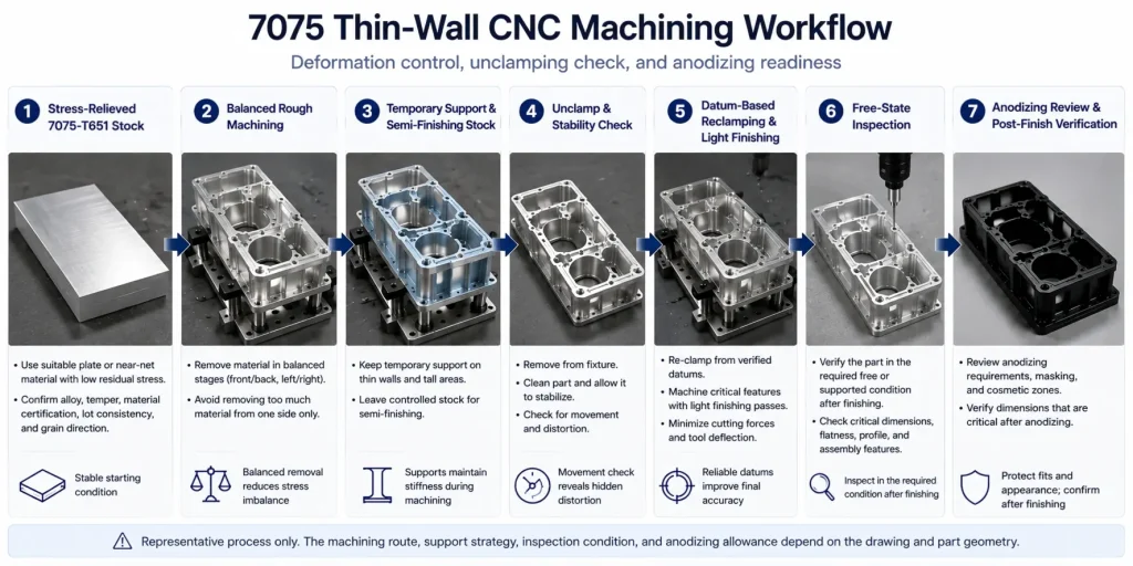
No single toolpath works for every part, but the following sequence provides a useful planning framework.
1. Start With Appropriate Stock
Review whether the part should be made from:
- Plate
- Bar
- Extrusion
- Forging
- Near-net material
For a heavily pocketed plate component, stock condition and stress relief may matter more than choosing the lowest raw-material price.
Also check:
- Stock flatness
- Surface condition
- Extra material for workholding
- Grain direction
- Material lot consistency
- Certification requirements
2. Establish Stable Datums First
The first operation should create reliable locating surfaces without removing so much material that the part becomes unstable immediately.
A good datum plan should support:
- Repeatable reclamping
- Access to critical features
- Inspection after unclamping
- Consistent orientation between machining and CMM inspection
- Surface-treatment masking references where required
3. Rough the Part in Balanced Stages
Avoid completely roughing and finishing one side while the opposite side remains fully solid when that sequence creates an unbalanced stress release.
Depending on the geometry, the process may alternate between:
- Front and back surfaces
- Opposing pockets
- Inner and outer walls
- Symmetrical regions of a frame
The goal is not perfect geometric symmetry. It is controlled removal that avoids concentrating all deformation in one stage.
4. Keep Temporary Support
Weak walls may benefit from temporary material such as:
- An onion skin
- Support tabs
- Temporary ribs
- A connecting web
- Extra floor thickness
- A sacrificial perimeter
These features keep the component rigid during roughing and are removed later with lighter engagement.
Temporary supports must be planned so their final removal does not damage cosmetic surfaces or critical edges.
5. Leave Controlled Semi-Finishing Stock
Do not rough directly to the final wall size.
A semi-finishing allowance provides room to correct:
- Roughing deflection
- Stock movement
- Tool marks
- Local taper
- Fixture-related distortion
The correct allowance depends on wall height, cutter reach, part size, and expected material movement. One fixed value should not be applied to every component.
6. Release, Stabilize, and Recheck
For deformation-sensitive parts, an intermediate release can reveal movement that was hidden by the first fixture.
The workflow may include:
- Rough machining
- Unclamping
- Cleaning and deburring
- Allowing the part to stabilize
- Checking movement
- Reclamping from confirmed datums
- Semi-finishing or finishing
This does not guarantee that all movement disappears. It allows the final process to respond to the part’s actual condition instead of assuming that the rough-machined geometry remained unchanged.
7. Finish Critical Features With Low and Stable Cutting Forces
The final operation should prioritize repeatability rather than maximum material-removal rate.
Typical considerations include:
- Small, controlled radial engagement
- A consistent finishing allowance
- Sharp cutting edges
- Short tool overhang
- Stable tool entry and exit
- Reliable chip evacuation
- Minimal recutting
- Separate finishing tools for critical surfaces
- Tool wear control across the batch
A spring pass is not automatically a solution. If the wall is deflecting away from the cutter, repeating the same toolpath may produce little improvement or may create additional rubbing.
Fixture Design and Clamping Pressure
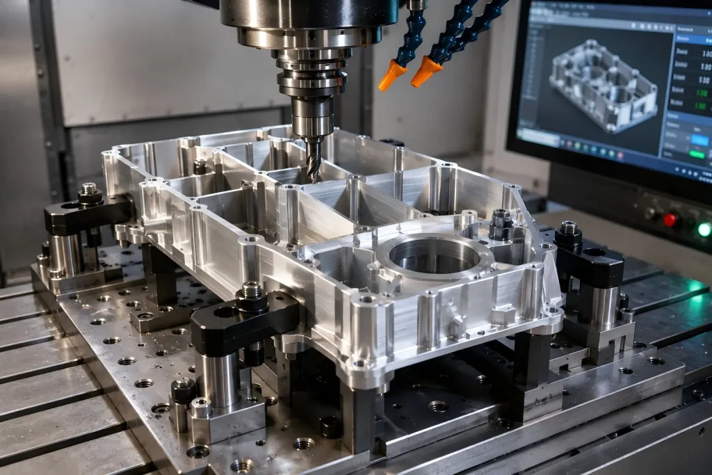
A fixture for a thin-wall component should support the part without forcing it into a false shape.
Useful approaches may include:
- Machined soft jaws
- Distributed support pads
- Low-force clamps
- Modular support close to the cutting zone
- Internal mandrels
- Sacrificial carriers
- Vacuum fixtures for suitable flat geometries
- Adhesive or encapsulation methods for selected special cases
Vacuum workholding is not automatically the best choice. It depends on:
- Available sealing area
- Cutting direction
- Leakage risk
- Part flatness
- Required holding force
- Surface-protection needs
The fixture should be reviewed in three conditions:
- Before clamping
- While clamped
- After release
If the part only meets tolerance under clamp pressure, the fixture may be hiding the actual deformation.
For general thin-wall strategies across different aluminum grades, review our thin-wall aluminum CNC machining guide.
Cutter Geometry, Tool Reach, and Chip Control
7075 machines well with suitable cutting tools, but a high-strength alloy and weak wall create a process where tool pressure matters.
A practical aluminum tool normally uses:
- Sharp cutting edges
- Positive cutting geometry
- Smooth or polished flutes
- Adequate chip space
- Suitable helix and core geometry
- Low runout
- A rigid holder
The tool should be:
- As large as the geometry allows
- As short as the feature allows
- Long enough to clear the wall without unnecessary stickout
Long-reach tools increase:
- Deflection
- Chatter risk
- Wall taper
- Corner wear
- Sensitivity to runout
Chip evacuation is equally important. Recut chips can scratch a finished wall, increase cutting force, and damage a thin edge.
The coolant or air strategy should remove chips reliably without applying uncontrolled pressure to a delicate wall.
Common Problems and Likely Causes
| Observed problem | Possible causes | Process checks |
|---|---|---|
| Wall is oversized near the middle | Wall deflecting away from the cutter | Reduce cutting force, support the wall, revise finishing engagement |
| Wall is tapered | Tool deflection, long reach, unstable clamping | Shorten tool, reduce engagement, inspect holder runout |
| Part bows after unclamping | Residual stress release or clamp distortion | Review stock condition, balanced roughing, intermediate release |
| Chatter marks appear on tall walls | Low wall stiffness, unstable tool engagement | Add temporary support, change toolpath, reduce overhang |
| Pocket width changes after machining | Opposing walls moved after release | Inspect in free state, revise roughing sequence |
| Flatness changes after anodizing | Coating, pretreatment, handling, or existing part stress | Define pre- and post-finish inspection requirements |
| Burrs form on thin exits | Dull edge, unsupported exit, incorrect feed | Use sharp tooling and controlled exit strategy |
| Color varies after anodizing | Alloy chemistry, stock variation, pretreatment, surface texture | Control material lot and approved visual standard |
Inspect the Part After Unclamping
Inspection performed only while the part is clamped may not represent the delivered component.
The inspection plan should identify:
- Datum A, B, and C
- Free-state or restrained-state condition
- Support-point locations
- Stabilization time, when required
- Temperature requirements
- Critical wall-thickness locations
- Profile, flatness, parallelism, and position requirements
- Features requiring functional gauges
- Pre-anodize and post-anodize checks
- Report format
Possible inspection equipment includes:
- CMM
- Height gauge
- Surface plate
- Micrometer
- Caliper
- Bore gauge
- Pin or plug gauges
- Dedicated checking fixture
- Optical measurement equipment
The method must suit the feature. A flexible wall can move under a measuring probe, so measurement force and part support can affect the result.
Tight tolerances should be assigned only to features that control function. Applying the same tight requirement to every wall, pocket, and cosmetic surface increases machining and inspection cost without necessarily improving the assembly.
Anodizing Risks on 7075 Aluminum
7075 can be anodized, but its cosmetic result should not be assumed to match 6061.
Alloy chemistry affects the natural tone and response to pretreatment and dyeing. Higher-alloyed 7075 may produce a darker or less uniform appearance, and light decorative colors may be more difficult to match consistently.
The Aluminum Anodizers Council notes that anodizing results depend on the alloy and desired outcome, while finishing guidance commonly identifies high-strength alloys such as 7075 as more difficult to color-match than 6000-series aluminum.
Control the Material Source
For appearance-sensitive batches, try to keep consistent:
- Alloy
- Temper
- Product form
- Material supplier
- Material lot
- Grain direction
- Machined surface condition
Mixing stock from different sources or lots may increase visible variation.
Define the Visual Standard
Words such as:
- Black
- Clear
- Uniform
- Matte
- Satin
- No color difference
are not sufficient on their own.
Specify whether acceptance is based on:
- An approved physical sample
- A defined color range
- A gloss range
- A visual distance and lighting condition
- Separate cosmetic zones
- A first-article approval
A generated rendering or CAD color should not be treated as an anodizing color standard.
Do Not Treat Bead Blasting as a Color Guarantee
Bead blasting can help create a more uniform surface texture, but it cannot guarantee identical anodized color across every 7075 batch.
The final appearance is also affected by:
- Alloy chemistry
- Surface preparation
- Existing tool marks
- Media condition
- Bath control
- Coating thickness
- Dyeing
- Sealing
Protect Fits, Holes, and Threads
Anodizing changes the surface and can affect:
- Precision bores
- External diameters
- Thread fit
- Bearing seats
- Grounding surfaces
- Electrical-contact areas
- Sealing interfaces
Depending on the drawing, these features may require:
- Masking
- Machining allowance
- Post-anodize verification
- Thread plugging
- Controlled coating thickness
- Secondary machining
Dimensions should clearly state whether they apply before or after anodizing.
For a wider comparison of anodizing, bead blasting, coating allowances, masking, and inspection, review our surface finishes for CNC parts.
DFM Questions to Confirm Before Quotation
Before machining a 7075 thin-wall part, the buyer and supplier should confirm:
- Is 7075 required by load calculation, or would 6061 provide sufficient performance?
- What temper and stock form are required?
- What is the minimum wall thickness?
- What is the unsupported wall height and span?
- Which dimensions are functionally critical?
- Which surfaces are datums?
- Is the part inspected in a free or restrained condition?
- Are ribs, fillets, or temporary supports allowed?
- Is the part anodized?
- Which dimensions apply after anodizing?
- Are any bores, threads, or contact areas masked?
- Does cosmetic appearance require an approved sample?
- Are material certificates or inspection reports required?
- Is the quantity a prototype, low-volume batch, or repeat order?
- Is assembly-level inspection required?
Answering these questions before production usually provides more value than applying an extremely tight tolerance to the complete drawing.
7075 vs 6061 for Thin-Wall Parts
7075 is not automatically the best alloy simply because it is stronger.
| Requirement | 6061 | 7075 |
|---|---|---|
| General machinability | Very good | Very good with suitable tooling |
| Strength | Moderate | Higher |
| Dimensional-stability risk | Often easier to manage | Requires careful review of stock and process |
| Cosmetic anodizing | Usually easier to control | May be darker or more variable |
| Corrosion resistance | Generally better | Lower than 6061 in many environments |
| Cost | Usually lower | Usually higher |
| Typical choice | General housings and fixtures | High-load lightweight structural components |
Choose 7075 when its mechanical performance is needed. Do not select it only because it sounds more advanced.
FAQ
What Is Considered a Thin-Wall 7075 Part?
There is no universal thickness limit.
Wall behavior depends on its height, length, shape, support, nearby ribs, cutter reach, and the amount of surrounding material. A 1 mm wall may be stable in a small supported feature but difficult across a large housing.
Is 7075-T651 Better Than 7075-T6 for Machining?
For plate components, T651 is often preferred when reduced residual-stress risk is important because it has been stress-relieved by stretching.
It still does not eliminate movement caused by unbalanced machining, weak geometry, excessive clamping, or cutting heat.
Can a 7075 Thin-Wall Part Hold ±0.02 mm?
Selected dimensions may be achievable after engineering review, but ±0.02 mm should not be promised for every wall or across an entire large component.
Capability depends on feature size, wall stiffness, datum structure, machining sequence, inspection state, and surface treatment.
Why Does the Part Move After the Clamps Are Released?
The fixture may be elastically deforming the component, or machining may have changed the balance of residual stress in the stock.
After clamp pressure is removed, the part moves toward its free-state shape.
Can 7075 Be Black Anodized?
Yes, 7075 can be black anodized.
However, shade, gloss, and uniformity may differ from 6061. Material lot, pretreatment, surface texture, coating process, dyeing, and sealing all affect the final result.
Should Dimensions Be Checked Before or After Anodizing?
It depends on the feature.
Critical fits, bores, threads, sealing surfaces, and assembly interfaces may need post-anodize verification. The drawing should identify which dimensions apply to the finished condition.
Can Bead Blasting Eliminate Anodizing Color Variation?
No.
Bead blasting can make the texture more consistent, but it cannot remove variation caused by alloy chemistry, stock condition, bath control, coating thickness, dyeing, or sealing.
Should Thin Walls Be Finished in One Pass?
Usually not as a universal strategy.
A controlled roughing, semi-finishing, release, reclamping, and finishing sequence may provide better stability. The exact route depends on the geometry and quantity.
Review Your 7075 Thin-Wall Part Before Production
Send the complete project information, including:
- STEP or other 3D CAD file
- 2D drawing
- 7075 alloy and temper
- Quantity
- Critical tolerances
- Datum requirements
- Minimum wall thickness
- Anodizing specification
- Cosmetic zones
- Masking requirements
- Inspection and reporting needs
- Assembly requirements
Rapid Efficient can review the geometry, material condition, tool access, fixture risks, machining sequence, surface-finishing requirements, and inspection priorities before quotation.
For prototype, low-volume, and repeat projects, review our CNC aluminum machining services.