Aluminum is generally easier to cut than many steels, but that does not mean every aluminum part is easy to manufacture.
Its relatively low hardness, adhesion tendency, thermal expansion, visible surface requirements, and sensitivity to thin-wall clamping can expose weaknesses in:
- Tool selection
- Cutting parameters
- Tool runout
- Chip evacuation
- Workholding
- Machining sequence
- Temperature control
- Inspection
- Deburring
- Surface finishing
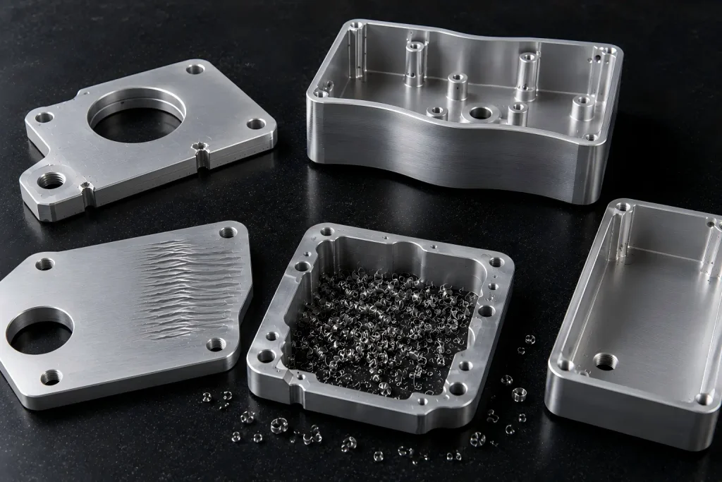
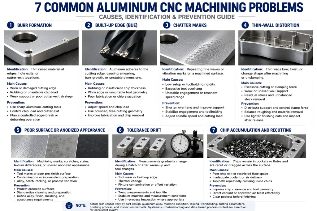
The seven most common aluminum machining problems are:
- Burr formation
- Built-up edge
- Chatter and vibration marks
- Thin-wall deformation
- Poor surface or anodized appearance
- Tolerance drift
- Chip accumulation and surface recutting
The correct solution depends on the alloy, feature, machine, tool, setup, quantity, finish, and inspection requirement. No single cutter, coating, fixture, feed rate, or coolant method solves every aluminum machining problem.
Quick Answer
When an aluminum CNC part develops a quality problem, check the process in this order:
- Confirm the actual symptom instead of using a general description such as “bad finish.”
- Identify whether the defect repeats in the same location.
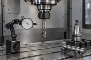
- Inspect the cutting edge, tool runout, holder, and tool projection.
- Check chip load, engagement, cutting speed, and finishing allowance.
- Clean the fixture, jaws, locating surfaces, and workpiece.
- Verify chip evacuation from pockets, slots, holes, and finished faces.
- Review clamping pressure and thin-wall support.
- Compare the first part with later parts for tool wear or thermal drift.
- Confirm whether the requirement applies before or after anodizing or coating.
- Make sure the inspection method matches the drawing and datum structure.
Do not correct every problem by reducing the feed rate. Excessive rubbing can increase heat, adhesion, burrs, and unstable surface finish.
Aluminum Machining Problem Summary
| Problem | What it looks like | Common causes | First checks |
|---|---|---|---|
| Burr formation | Sharp lips, rolled material, or feather edges | Dull edge, poor exit, weak support, unsuitable chip load | Cutting edge, exit direction, burr location, tool wear |
| Built-up edge | Smeared surface, torn finish, changing dimensions | Aluminum adhesion, rubbing, heat, worn tool, poor lubrication | Tool edge, chip shape, cutting parameters, coolant delivery |
| Chatter | Repeated waves or vibration marks | Low rigidity, long tool, unstable engagement, thin wall | Tool overhang, holder runout, fixture, spindle-speed range |
| Thin-wall deformation | Wall bends during machining or changes after release | Clamping force, cutting force, residual stress, uneven stock removal | Free-state measurement, jaw pressure, roughing sequence |
| Poor anodized appearance | Visible lines, scratches, stains, or uneven texture after finishing | Pre-finish defects, contamination, alloy variation, inconsistent preparation | Surface before finish, alloy, blasting, handling, rack areas |
| Tolerance drift | Early parts pass but later parts move out of specification | Tool wear, temperature, fixture contamination, offset changes | Trend data, tool life, coolant temperature, measurement method |
| Chip recutting | Random scratches, packed pockets, unstable load, damaged edges | Poor evacuation, restricted flute space, trapped chips | Pocket condition, flute geometry, coolant or air delivery |
1. Burr Formation on Aluminum Edges
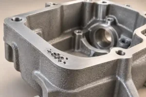
Burrs are unwanted projections of material left around an edge after milling, drilling, turning, slotting, or thread preparation.
They may appear as:
- Thin feather burrs
- Rolled lips
- Heavy exit burrs
- Burrs around drilled holes
- Raised material around cross holes
- Sharp edges on thin walls
- Smeared material near a finished face
Common Causes
Burr formation may be linked to:
- Worn or damaged cutting edges
- Excessive rubbing
- Unsuitable chip load
- Poor tool exit direction
- Weak support near the edge
- Excessive tool deflection
- Thin material at the exit
- Built-up edge
- Incorrect drilling breakthrough strategy
- An edge left unsupported during the final pass
What to Check First
Determine where the burr appears.
A burr that always forms on one side may indicate:
- A predictable cutter exit
- Part orientation
- Tool rotation direction
- Local lack of support
- Uneven tool wear
A burr that becomes larger over time may indicate progressive tool wear or built-up edge.
How to Reduce the Risk
Depending on the operation, the process may use:
- A sharp tool suitable for aluminum
- Controlled chip load
- A toolpath that places the exit on a noncritical edge
- Reduced unsupported material at breakthrough
- A dedicated chamfer or edge-break operation
- Backing support for thin features
- Tool replacement based on wear condition
- Controlled manual or mechanical deburring
Do not use aggressive deburring to hide a machining problem. Excessive blending can alter edge dimensions, cosmetic faces, hole entrances, sealing surfaces, or anodized appearance.
2. Built-Up Edge and Aluminum Adhesion
Built-up edge occurs when workpiece material adheres to the cutting edge.
The attached aluminum changes the effective cutting geometry. Instead of cutting cleanly, the tool may begin to rub, tear, smear, or intermittently release adhered material onto the part.
Possible signs include:
- Rough or torn surface finish
- Shiny smeared areas
- Changing cutting noise
- Increasing burr size
- Unstable dimensions
- Material stuck to the cutter
- Sudden changes in spindle load
- Scratches caused by released material
- Shortened tool life
Common Causes
Built-up edge may be promoted by:
- Worn or rounded cutting edges
- Excessive rubbing
- Insufficient chip thickness
- Unstable cutting temperature
- Poor chip evacuation
- Inadequate lubrication
- Unsuitable tool geometry
- Too much tool runout
- Recutting trapped chips
What to Check First
Inspect:
- Cutting-edge condition
- Flute condition
- Chip shape
- Toolholder runout
- Tool projection
- Coolant or lubricant delivery
- Actual chip load
- Whether the tool is cutting or rubbing
How to Reduce the Risk
Possible improvements include:
- Sharp, free-cutting geometry
- Polished flute surfaces
- Suitable flute space
- Stable chip load
- Reduced unnecessary rubbing
- Effective coolant or lubrication
- Reliable chip removal
- Controlled tool runout
- A dedicated finishing tool
- A coating selected for the alloy and operation where useful
DLC, TiB2, ZrN, polished uncoated carbide, and other options may all be useful under the correct conditions. None should be treated as a universal requirement.
For a detailed comparison of flute count, cutter geometry, coatings, tool reach, and feature-specific selection, review our aluminum milling cutter selection guide.
For spindle speed, cutting speed, chip load, and feed relationships, review our practical guide to cutting speed for aluminum milling.
3. Chatter and Vibration Marks
Chatter is an unstable vibration between the cutting tool, workpiece, machine, and fixture.
It often produces:
- Regular wave patterns
- Repeating diagonal marks
- Uneven wall finish
- Excessive noise
- Changing spindle load
- Poor dimensional repeatability
- Tool chipping
- Thin-wall movement
Chatter is common when machining:
- Deep pockets
- Tall walls
- Long-reach features
- Thin ribs
- Small internal corners
- Weakly supported parts
- Features requiring long tool projection
Common Causes
- Excessive tool overhang
- Weak toolholding
- Poor fixture rigidity
- Thin unsupported walls
- Tool runout
- Unstable radial engagement
- A resonant spindle-speed range
- Excessive cutting force
- Interrupted cuts
- Loose fixture components
- Worn spindle or holder interfaces
What to Check First
Before changing every parameter, inspect:
- Tool projection
- Tool diameter
- Holder condition
- Fixture contact
- Clamp position
- Part support
- Spindle-speed response
- Cutting direction
- Engagement changes at corners
- Whether the marks occur during roughing or finishing
How to Reduce the Risk
Possible actions include:
- Shortening tool projection
- Increasing setup rigidity
- Supporting the feature closer to the cut
- Using a larger tool where geometry allows
- Reducing abrupt engagement changes
- Adjusting the spindle-speed range
- Separating roughing and finishing
- Leaving a controlled finishing allowance
- Using lighter finishing passes
- Reviewing variable-helix or other vibration-control tooling
- Reducing cutting force on thin features
Do not assume that a lower spindle speed always eliminates chatter. Moving away from a resonant range may require increasing or decreasing speed depending on the system.
4. Thin-Wall Aluminum Deformation
Thin-wall aluminum parts may move during cutting, after unclamping, during deburring, or after surface treatment.
A wall can appear acceptable while restrained in the fixture and change after release.
Typical symptoms include:
- Bowed walls
- Out-of-flat faces
- Bore ovality
- Uneven wall thickness
- Position shift
- Opening or closing slots
- Distorted sealing surfaces
- Dimensions that change between setups
Common Causes
- Excessive clamping force
- Small jaw contact areas
- High cutting force
- Unbalanced material removal
- Uneven stock
- Residual stress in the material
- Heavy roughing near a finished wall
- Insufficient support
- Heat accumulation
- Measuring only while the part is restrained
What to Check First
Confirm:
- Whether the part is measured in the free state
- Clamping force and contact area
- Wall thickness near the defect
- Roughing sequence
- Stock removed from each side
- Time between roughing and finishing
- Datum location
- Whether the fixture is forcing the part into shape
How to Reduce the Risk
Depending on the design, the process may include:
- Larger or more distributed support areas
- Lower controlled clamping force
- Purpose-built soft jaws
- Sacrificial tabs
- Temporary support material
- Balanced roughing
- Symmetrical material removal
- Staged roughing and finishing
- A controlled finishing allowance
- Lighter finishing cuts
- Requalification of datums between stages
- Free-state inspection after unclamping
Vacuum workholding or an onion-skin strategy may help selected flat or thin components, but neither is appropriate for every housing, rib, bore, or irregular part.
5. Poor Surface or Anodized Appearance
A machined aluminum part may look acceptable immediately after cutting but develop visible problems after bead blasting, brushing, polishing, anodizing, painting, or handling.
Possible defects include:
- Cutter lines
- Chatter marks
- Random scratches
- Mixed surface texture
- Uneven polishing
- Dents
- Embedded contamination
- Edge damage
- Anodized color variation
- Rack marks
- Stains
Anodizing usually does not hide machining marks, scratches, or uneven preparation. Some defects may become easier to see after finishing.
Common Causes
- Inconsistent finishing passes
- Tool re-entry on visible surfaces
- Chips dragged across the part
- Dirty fixtures or trays
- Aggressive deburring
- Uneven bead blasting
- Different alloys or material batches
- Inconsistent surface preparation
- Contamination before finishing
- Poorly defined cosmetic surfaces
What to Check First
Compare the surface:
- Directly after machining
- After deburring
- After cleaning
- Before surface treatment
- After surface treatment
This identifies the stage where the defect first appears.
How to Reduce the Risk
- Mark cosmetic surfaces on the drawing.
- Use a controlled finishing strategy.
- Protect visible faces during unloading.
- Separate parts during internal transport.
- Keep trays, gloves, cloths, and fixtures clean.
- Define blasting, brushing, or polishing requirements.
- Confirm alloy and material batch where color is critical.
- Define rack and masking areas.
- Inspect parts before and after finishing.
- Package cosmetic parts without metal-to-metal contact.
6061 is frequently considered for cosmetic anodized parts because it offers a practical combination of availability, machining, corrosion behavior, and finishing response. It is not automatically the correct alloy when strength, temperature, welding, fatigue, or another function requires a different grade.
For more detail on cleaning, inspection, part separation, internal transport, and packaging, review our guide on how to prevent scratches on CNC aluminum parts.
For color variation, rack marks, burns, pitting, stains, poor sealing, and other finishing risks, review our aluminum anodizing defects guide.
For a broader comparison of anodizing, bead blasting, polishing, painting, powder coating, plating, and other options, review our guide to surface finishes for CNC-machined parts.
6. Tolerance Drift During Production
Tolerance drift occurs when the first parts meet the drawing but measurements gradually change during the batch.
The shift may be continuous, intermittent, or linked to a tool change, machine restart, fixture cleaning, or temperature change.
Common Causes
- Progressive tool wear
- Built-up edge
- Machine warm-up
- Coolant-temperature change
- Workpiece-temperature change
- Fixture contamination
- Chips under locating surfaces
- Toolholder runout
- Offset-entry errors
- Probe-calibration changes
- Measurement-method variation
- Clamping inconsistency
- Material movement
What to Check First
Trend measurements by part number or production time.
Compare:
- First part
- Warm machine condition
- Mid-batch parts
- Parts before and after a tool change
- Parts before and after fixture cleaning
- Parts measured by different operators or instruments
A gradual trend often indicates tool wear or thermal change. A sudden step may indicate a tool, offset, fixture, datum, or measurement change.
How to Reduce the Risk
The production plan may include:
- Tool-life limits
- In-process inspection
- Scheduled fixture cleaning
- Stable machine warm-up
- Controlled coolant condition
- Calibrated probing
- Defined offset-adjustment rules
- SPC for suitable production volumes
- First-off verification after tool changes
- Measurement at an agreed temperature
- Correlation between shop-floor and final inspection equipment
Probe-based offset correction can be useful, but automatic correction should not hide tool damage, fixture movement, part deformation, or an unstable process.
7. Chip Evacuation and Surface Recutting
Aluminum chips may be long, curled, fragmented, sticky, or packed into pockets depending on the alloy, operation, tool, and cutting conditions.
When chips remain in the cutting area, they may:
- Be recut by the tool
- Scratch finished surfaces
- Pack into flutes
- Increase cutting load
- Damage the cutting edge
- Block coolant delivery
- Become trapped under the workpiece
- Create poor hole quality
- Increase cycle time
- Cause unexpected tool failure
High-Risk Features
- Deep pockets
- Narrow slots
- Blind holes
- Horizontal ledges
- Deep drilled holes
- Long-reach milling
- Fixtures with poor drainage
- Parts containing several enclosed cavities
What to Check First
Inspect:
- Chip accumulation in the feature
- Flute space
- Tool engagement
- Coolant direction
- Through-tool delivery where available
- Air-blast direction where permitted
- Pocket clearing and retract paths
- Whether the tool repeatedly passes through loose chips
How to Reduce the Risk
Depending on the machine and workplace procedure:
- Use suitable flute geometry and chip space.
- Direct coolant toward the cutting zone.
- Use through-tool delivery where applicable.
- Use air blast only where permitted and safely controlled.
- Add planned chip-clearing moves.
- Avoid trapping chips at the bottom of the pocket.
- Separate roughing and finishing operations.
- Clean fixtures before reloading parts.
- Keep finished surfaces away from loose chips.
- Review the toolpath when chips are repeatedly pulled back into the cut.
High pressure is not automatically better. The delivery direction, volume, tool geometry, enclosure, safety procedure, and chip exit path matter.
Diagnostic Sequence for Aluminum Machining Problems
When a defect appears, use a controlled diagnostic sequence.
Step 1: Define the Defect
Record:
- Defect location
- Direction
- Frequency
- Depth or severity
- Whether it repeats
- Whether it appears before or after finishing
- Whether the dimension changes after unclamping
Step 2: Check the Tool
Inspect:
- Cutting edge
- Flutes
- Coating condition
- Material adhesion
- Chipping
- Runout
- Tool projection
- Holder condition
Step 3: Check the Setup
Inspect:
- Jaws and locators
- Chips under the part
- Clamp pressure
- Fixture rigidity
- Part support
- Datum contact
- Part seating
Step 4: Check the Cutting Process
Review:
- Cutting speed
- Feed per tooth
- Axial and radial engagement
- Entry and exit
- Corner engagement
- Roughing allowance
- Finishing strategy
- Coolant or lubrication
- Chip evacuation
Step 5: Check Measurement and Finishing
Confirm:
- Instrument and calibration
- Datum alignment
- Part temperature
- Free or restrained condition
- Inspection stage
- Surface-treatment allowance
- Cosmetic acceptance standard
- Packaging and handling
Change one meaningful factor at a time where practical. Changing the tool, speed, feed, fixture, coolant, and program simultaneously makes it difficult to identify the real cause.
Buyer RFQ Checklist for Aluminum CNC Parts
Provide the following before quotation:
- 3D CAD model
- Controlled 2D drawing
- Aluminum alloy and temper
- Stock form
- Quantity
- Critical dimensions
- Datum structure
- Thin-wall areas
- Deep pockets and slots
- Cosmetic surfaces
- Required edge break
- Surface roughness where functional
- Anodizing, painting, plating, blasting, or polishing
- Masking areas
- Threads and precision fits
- Free-state or restrained inspection requirement
- CMM or dimensional-report requirement
- Material-certificate requirement
- Approved cosmetic sample where available
- Packaging and part-separation requirements
- Known problems from previous production
A previous rejected sample, defect photograph, or inspection report can help identify whether the problem originated from machining, handling, finishing, or measurement.
How Rapid Efficient Supports CNC Aluminum Parts
Rapid Efficient supports custom CNC-machined aluminum prototypes, low-volume parts, and repeat production for:
- Housings
- Brackets
- Plates
- Frames
- Covers
- Heat sinks
- Motor mounts
- Bearing carriers
- Automation components
- Optical and electronic equipment parts
Project support may include:
- Drawing and DFM review
- Alloy and stock-form review
- CNC milling and turning
- Tooling and workholding planning
- Thin-wall risk review
- Cosmetic-surface identification
- Surface-finishing coordination
- Dimensional inspection
- CMM reports when requested
- Material documentation when requested
- Part separation and packaging
- International delivery coordination
Final feasibility depends on the alloy, geometry, wall thickness, tolerance, finish, quantity, inspection scope, and packaging requirement.
Learn more about our CNC aluminum machining services for custom prototypes, low-volume components, and repeat production.
After receiving complete drawings, CAD files, quantities, finishing requirements, and inspection expectations, Rapid Efficient typically provides quotation feedback within 24 hours.
FAQ
Why does aluminum form burrs so easily?
Many aluminum alloys are ductile and may bend or smear at an unsupported edge instead of separating cleanly. Tool condition, chip load, exit direction, wall support, and built-up edge all affect burr formation.
Why does aluminum stick to cutting tools?
Aluminum may adhere to the cutting edge under pressure and heat, especially when the edge is worn, the process causes rubbing, lubrication is insufficient, or chips are not removed effectively.
Is 6061 the easiest aluminum to machine?
6061-T6 is a practical and widely available machining alloy, but the best choice still depends on strength, finish, corrosion, welding, stock form, dimensional stability, and cost. Free-machining alloys may cut more easily but may not meet the project’s functional requirements.
Why do thin aluminum walls move after machining?
Clamping force, cutting force, heat, uneven stock removal, and residual stress can deform the part. Some movement only becomes visible after the fixture is released.
Why do scratches become visible after anodizing?
Anodizing generally follows the existing aluminum surface. Machining marks, handling scratches, polishing differences, or inconsistent preparation may remain visible or become easier to notice.
Why do dimensions drift during a production run?
Common causes include tool wear, built-up edge, thermal change, fixture contamination, inconsistent clamping, offset changes, and measurement variation.
Can reducing feed solve poor surface finish?
Not always. An excessively low feed may cause rubbing, heat, adhesion, and unstable cutting. Surface problems should be diagnosed using tool condition, chip load, cutting speed, engagement, rigidity, and chip evacuation together.
Is air blast always required for aluminum machining?
No. Depending on the machine and operation, chip removal may use coolant, through-tool delivery, air blast where safely permitted, or another approved method. The correct choice depends on chip behavior, part geometry, machine enclosure, safety, and finish requirements.
Does bead blasting hide machining defects?
Bead blasting can create a more uniform texture, but deep scratches, dents, chatter, uneven deburring, and major tool marks may remain visible.
When should a finishing tool be replaced?
Tool replacement should be based on wear, finish trend, burr growth, dimensional trend, cutting load, noise, and production requirements rather than only a fixed time value.
Request an Aluminum Machining Review
Send Rapid Efficient your:
- 2D drawing
- 3D model
- Aluminum grade
- Quantity
- Critical tolerances
- Cosmetic surfaces
- Finish requirements
- Previous defect photos or reports
- Inspection expectations
- Packaging requirements
We can review the likely causes of burrs, built-up edge, chatter, deformation, poor finishing appearance, tolerance drift, and chip recutting before production begins.