Choosing between aluminum and plastic is not simply a question of which material is stronger or cheaper.
The decision usually contains two separate questions:
- Should the part behave like a metal or like an engineering polymer?
- Should it be CNC machined, injection molded, or produced through a combination of processes?
These questions should not be mixed together.
A CNC-machined POM guide block is not the same type of product as an injection-molded ABS cover. A PEEK electrical isolator is not a lower-cost version of an aluminum mounting bracket. Each material and manufacturing route solves a different problem.
Use aluminum when the part must remain rigid, spread heat, support durable threads, carry clamping loads, or form part of a conductive enclosure. Use engineering plastic when electrical insulation, low friction, chemical compatibility, reduced weight, or controlled flexibility matters more. Choose injection molding only after the plastic design and production quantity justify dedicated tooling.
First Separate the Material Decision From the Process Decision
“Aluminum versus plastic” can describe several different comparisons.
| Comparison | What You Are Really Deciding |
|---|---|
| CNC-machined aluminum vs CNC-machined plastic | Which material behavior is more suitable for the part |
| CNC-machined aluminum vs injection-molded plastic | Both the material and the manufacturing route |
| Aluminum structure with plastic components | How to assign different functions within one assembly |
| CNC plastic prototype vs molded plastic production part | Whether the design is mature enough for tooling |
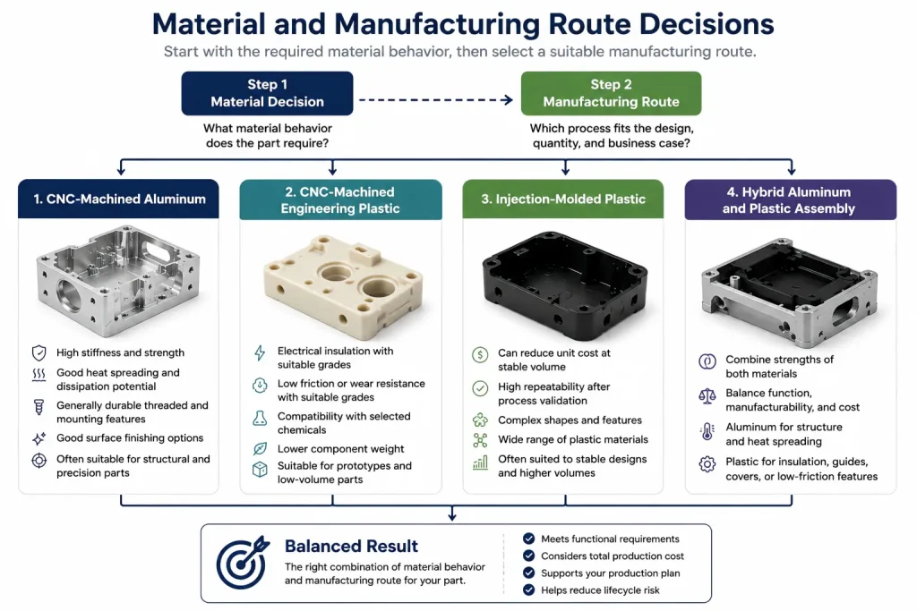
This distinction matters because manufacturing economics can hide the real engineering requirement.
A molded plastic housing may have a low unit cost at stable volume, but that does not make plastic suitable for a heat-spreading base or highly loaded mounting plate. A CNC-machined aluminum part may avoid mold investment, but that does not make aluminum the correct material for an electrical isolator or low-friction guide.
Start with the function. Choose the manufacturing route after the required material behavior is clear.
Aluminum Is Usually the Safer Starting Point for Rigid Structures
Aluminum is commonly selected for parts that must maintain geometry under fastening, vibration, machining, inspection, and repeated assembly.
Typical examples include:
- Equipment mounting plates
- Structural brackets
- Precision fixtures
- Robotic frames
- Motor mounts
- Electronics housings
- Optical or sensor supports
- Threaded covers
- Heat-spreading components
Its main advantage is not simply tensile strength. It is the combination of stiffness, machinability, thermal conductivity, available tempers, surface-finishing options, and predictable mechanical behavior.
This becomes important when a part includes:
- A machined datum surface
- A bearing or seal location
- Several threaded holes
- A wide flat mounting face
- Clamping loads from screws
- Alignment between separate components
- Features that must remain stable over time
The aluminum grade and temper still matter. A thin 5052 sheet enclosure, a 6061-T651 machined plate, and a 7075-T6 structural component do not behave the same way.
For a more detailed alloy comparison, review our guide to the best aluminum for CNC machining.
Engineering Plastic Is Not Just a Cheaper Substitute
Plastic is often treated as one material category. That is a mistake.
Engineering plastics can provide functions that aluminum cannot provide naturally, including:
- Electrical insulation
- Low friction
- Reduced noise
- Chemical compatibility
- Lower component weight
- Controlled flexibility
- Non-magnetic behavior
- Resistance to selected cleaning agents
- Transparent or translucent appearance
- Reduced wear against a mating component
The correct plastic depends on the operating environment.
POM
POM, also known as acetal, is often considered for precision guides, bushings, rollers, fixtures, and moving mechanical parts.
It can offer:
- Low friction
- Good wear behavior
- Relatively good dimensional stability
- Clean machining
- Lower moisture sensitivity than many nylon grades
It is not automatically suitable for every chemical or high-temperature environment.
Nylon
Nylon may be useful where toughness, impact behavior, wear resistance, and some flexibility are helpful.
However, moisture absorption can change:
- Dimensions
- Stiffness
- Weight
- Fits
- Long-term performance
The drawing and inspection plan should account for the actual nylon grade, conditioning state, and operating humidity.
PTFE
PTFE is selected mainly for low friction and broad chemical compatibility.
It also presents design challenges:
- Low stiffness
- High creep
- Difficult clamping
- Limited thread strength
- Dimensional movement under sustained load
It should not be evaluated using the same rules as POM or aluminum.
PEEK
PEEK may be suitable for demanding thermal, chemical, electrical, or mechanical environments.
It can solve problems that ordinary plastics cannot, but the exact grade matters. Unfilled, glass-filled, carbon-filled, bearing-grade, and medical-grade materials can behave differently.
Its material cost also makes unnecessary stock removal, rejected parts, and over-tight tolerances expensive.
ABS and Polycarbonate
ABS and polycarbonate are widely associated with housings, covers, guards, transparent features, and molded consumer or equipment components.
They should not be grouped automatically with machined POM, PTFE, or PEEK parts. Their design rules, production routes, surface expectations, and operating limits can be very different.
Our best plastics for CNC machining guide compares the main risks associated with POM, nylon, PTFE, PEEK, and other machinable polymers.
The Load After Assembly Matters More Than a One-Time Strength Test
Many material decisions are made by comparing a strength value on a datasheet.
That is not enough.
A part may pass a short test but move slowly after weeks or months under:
- Bolt preload
- Clamping pressure
- Spring force
- Bearing pressure
- Elevated temperature
- Vibration
- Repeated assembly
Many thermoplastics can creep or relax under sustained load. This may reduce clamping force, change alignment, loosen an assembly, or allow a sealing surface to move.
Plastic parts under long-term load may require:
- A wider load-bearing area
- Lower tightening torque
- Metal washers
- Compression limiters
- Threaded inserts
- Thicker bosses
- Additional ribs
- Reduced unsupported length
- A material grade selected for creep resistance
Aluminum can also distort when a part is thin, highly machined, poorly supported, or released from residual stress. It should not be treated as perfectly stable.
The difference is that aluminum is generally the more predictable starting point when the assembly depends on stiffness and sustained mechanical preload at ordinary equipment temperatures.
Tolerance Is a System Result, Not a Material Label
It is common to hear:
Aluminum can hold tight tolerances, while plastic cannot.
That statement is too simple.
POM, PEEK, and other selected engineering plastics can be machined into precision mechanical components. At the same time, a large thin-walled aluminum housing can distort after roughing, unclamping, anodizing, or temperature change.
The achievable result depends on:
- Material grade
- Material condition
- Stock form
- Internal stress
- Part geometry
- Wall thickness
- Tool sharpness
- Cutting heat
- Workholding
- Measurement temperature
- Time between machining and inspection
- Moisture conditioning
- Final operating environment
For plastic parts, a dimension measured immediately after machining may change after the part reaches a different temperature or moisture condition.
For aluminum parts, removing a large percentage of the original stock can release residual stress and change flatness.
The drawing should identify the dimensions that control function instead of placing tight tolerances on every feature. Datum relationships, mating conditions, inspection state, and operating environment are usually more important than a long list of isolated dimensions.
For further planning, see our CNC machining tolerances guide.
Threads and Inserts Decide How the Product Will Be Serviced
Thread design often reveals whether aluminum or plastic is the safer choice.
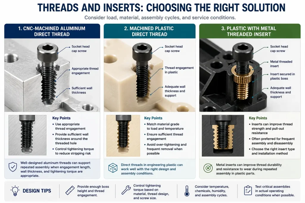
Direct Threads in Aluminum
Machined aluminum threads are commonly used for:
- Repeated assembly
- Machine screws
- Covers
- Fixtures
- Equipment brackets
- Housings
- Structural joints
They still require enough thread engagement, correct pilot-hole preparation, controlled tool wear, and suitable tightening torque.
Aluminum threads can strip, gall, become undersized after surface finishing, or fail when the thread is too close to a thin wall.
The choice between tapping and thread milling depends on the hole condition, thread size, depth, quantity, material, tool access, and scrap risk. These differences are explained in our thread milling vs tapping guide.
Direct Threads in Plastic
Directly machined plastic threads can work when:
- The assembly load is moderate
- The screw is not removed frequently
- The material has suitable stiffness
- The engagement length is sufficient
- Tightening torque is controlled
- The operating temperature is stable
They are not automatically weak, but the design must match the polymer.
Inserts in Plastic
Metal inserts deserve review when the assembly requires:
- Frequent removal and installation
- Higher tightening torque
- Better wear resistance
- More consistent preload
- Stronger pull-out resistance
- A metal-to-metal fastening interface
For molded plastic parts, inserts may be installed during molding or added through a secondary process. For machined plastic parts, press-fit, threaded, bonded, or heat-installed solutions may be possible depending on the material and geometry.
The insert method should be selected before the surrounding boss and wall thickness are finalized.
Heat Resistance and Heat Dissipation Are Different Requirements
A material that survives a high temperature does not necessarily remove heat effectively.
These are separate properties:
- Heat resistance describes whether the material retains acceptable performance at the operating temperature.
- Heat dissipation describes how effectively heat moves through the part and into another surface or the surrounding air.
Aluminum is commonly chosen when the part must spread heat away from:
- Power electronics
- LEDs
- Motors
- Batteries
- Sensors
- Communication equipment
- Heat-generating modules
Engineering plastics usually act more like thermal barriers than heat spreaders.
However, this does not mean aluminum is always the better material near heat. PEEK and other high-performance polymers may be selected when the part must tolerate temperature while also providing electrical insulation, chemical resistance, or reduced weight.
The correct question is not:
Which material is more heat resistant?
It is:
Must the part move heat, block heat, survive heat, or perform several of these functions at the same time?
A hybrid assembly may use an aluminum heat-spreading structure with plastic isolators, covers, spacers, or cable-management features.
An Aluminum Enclosure Does Not Automatically Solve EMI
Aluminum can support an electrically conductive enclosure, but EMI performance depends on the complete assembly.
Important details include:
- Seams between covers
- Fastener spacing
- Ventilation openings
- Connector cutouts
- Cable entry points
- Conductive gaskets
- Grounding paths
- Surface treatments
- Electrical contact between mating faces
Anodizing produces an electrically insulating oxide layer. That may be desirable for corrosion resistance or appearance, but it can interrupt an intended grounding path unless contact areas are masked or processed separately.
Plastic housings may require conductive coatings, internal shields, conductive fillers, or separate metal components when EMI control is required.
The enclosure must be evaluated as a system. Material selection alone does not confirm shielding performance.
Chemical Resistance Must Be Checked Against the Exact Environment
Neither “aluminum” nor “plastic” is universally corrosion-resistant.
Aluminum performance depends on:
- Alloy
- Temper
- Surface finish
- Coating
- pH
- Salt exposure
- Galvanic contact
- Cleaning chemicals
- Temperature
- Exposure time
Plastic performance depends on:
- Polymer family
- Fillers
- Stress level
- Temperature
- Chemical concentration
- Exposure duration
- Cleaning or sterilization cycle
A polymer may resist one chemical but swell, soften, crack, or lose strength in another environment.
Aluminum may resist normal atmospheric exposure but experience corrosion when connected to a dissimilar metal in the presence of an electrolyte.
The chemical name, concentration, operating temperature, and exposure method should be reviewed rather than relying on a general “chemical-resistant” label.
Production Volume Changes the Process, Not the Required Function
Injection molding can reduce unit cost after the design, mold, process, and production quantity justify the initial tooling investment.
That does not create a universal break-even quantity.
The real comparison depends on:
- Part size
- Resin
- Mold complexity
- Number of cavities
- Side actions
- Inserts
- Surface texture
- Color control
- Dimensional requirements
- Inspection
- Annual volume
- Expected design changes
- Tool maintenance
- Secondary machining
- Assembly requirements
CNC machining is often practical when:
- The design is still changing
- Quantity is limited
- Several versions are needed
- A high-performance stock-shape plastic is required
- Critical surfaces need machining
- Dedicated mold tooling is not yet justified
Injection molding becomes more attractive when:
- The plastic design is stable
- Wall thickness and draft are suitable
- Expected demand supports tooling
- The required resin can be processed reliably
- Changes after tool completion are unlikely
- Repeatable molded production is more important than design flexibility
A plastic prototype may be CNC machined before the final molded design is released. The prototype can check fit and general function, but it may not reproduce molded fiber orientation, shrinkage, weld lines, surface texture, internal stress, or boss behavior.
Our injection molding services page explains the production route for molded plastic components.
Practical Starting Points for Common Parts
The following table is a starting point, not a substitute for reviewing the drawing and service conditions.
| Part Requirement | Likely Starting Direction | Main Risk to Check |
|---|---|---|
| Rigid equipment mounting bracket | Aluminum | Wall thickness, distortion, fastener load |
| Heat-spreading electronics enclosure | Aluminum | Thermal interface, airflow, grounding, seams |
| Electrical isolator | Engineering plastic | Temperature, voltage, creep, chemical exposure |
| Low-friction guide or wear pad | POM, PTFE, or bearing-grade polymer | Creep, wear, mating material, lubrication |
| Frequently removed threaded cover | Aluminum or plastic with inserts | Thread engagement, torque, assembly cycles |
| Lightweight protective housing | Plastic or hybrid construction | Impact, UV, heat, screw bosses |
| Precision low-volume plastic manifold | CNC-machined engineering plastic | Stress, sealing faces, chemical compatibility |
| Stable high-volume consumer housing | Injection-molded plastic | Tooling, draft, wall thickness, cosmetic defects |
| Structural frame with insulation points | Aluminum plus plastic components | Thermal expansion and interface design |
| Transparent guard or viewing feature | Selected transparent polymer | Scratch resistance, chemical cleaning, impact |
In many assemblies, the best result is not a single-material design.
An aluminum chassis may provide stiffness and thermal control, while plastic parts provide insulation, cable routing, low-friction movement, touch-safe covers, or chemical separation.
The Drawing Should Describe the Service Condition
A material name alone is not enough to quote or manufacture the part correctly.
For aluminum, the drawing should identify the alloy and temper when they affect strength, machinability, appearance, or dimensional stability.
For plastic, it should identify the polymer grade and any glass, carbon, lubricant, bearing, medical, flame-retardant, or other modification.
The manufacturing review should also understand:
- Continuous and peak operating temperature
- Sustained mechanical load
- Clamping and tightening conditions
- Number of assembly cycles
- Moisture and chemical exposure
- Electrical insulation requirements
- Grounding or EMI requirements
- Critical mating surfaces
- Required dimensional condition
- Surface and appearance expectations
- Prototype and production quantities
- Whether the design is still expected to change
Without this information, a supplier may quote the drawing but still choose the wrong stock condition, tolerance strategy, fastening method, or manufacturing route.
Choose the Failure Mode You Cannot Accept
Aluminum is usually the safer choice when failure would come from:
- Loss of stiffness
- Heat buildup
- Thread wear
- Loss of alignment
- Insufficient clamping strength
- An incomplete conductive enclosure
Engineering plastic is usually worth reviewing when failure would come from:
- Electrical conduction
- Friction
- Chemical attack
- Excessive component weight
- Noise
- Metal-to-metal contact
- Lack of flexibility
Injection molding is a production decision made after the plastic material and design are suitable. It should not be used to justify plastic where the part still requires the stiffness, heat transfer, thread life, or structural behavior of aluminum.
For custom machined structures, our CNC aluminum machining services cover prototypes, low-volume parts, and repeat production. Projects involving engineering plastics or molded housings should be reviewed using the same drawing, service conditions, quantity, assembly requirements, and inspection expectations.
A good material decision does not begin with “metal or plastic?”
It begins with:
What must this part continue doing after machining, finishing, assembly, and real operating exposure?