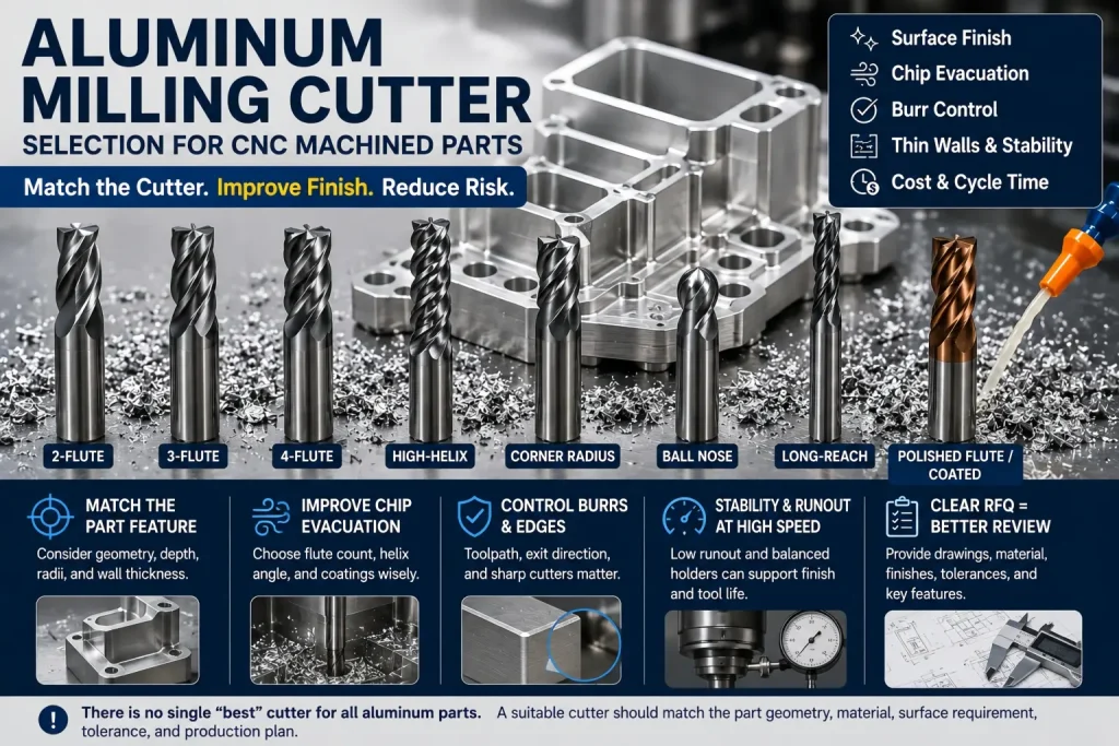
Choosing an aluminum milling cutter is not only a toolroom decision.
For CNC machined aluminum parts, the cutter can affect chip evacuation, burr formation, surface finish, thin-wall stability, tolerance control, tool wear, cycle time, and final inspection results.
A buyer usually does not need to specify the exact cutter brand.
But the buyer should understand when cutter choice becomes important.
The question is not only:
Which cutter is best for aluminum?
The better question is:
Which cutter geometry, flute count, coating, diameter, corner radius, and toolpath condition can protect this specific aluminum part from burrs, chatter, chip welding, distortion, and poor finish?
This guide explains how aluminum milling cutters are selected for CNC machined parts and what buyers should include in an RFQ when tooling affects part quality.
Aluminum Milling Cutter Selection Starts with the Part
There is no single cutter that works best for every aluminum part.
A cutter that works well for one simple 6061 plate may fail on a thin-wall housing, deep pocket, cosmetic cover, small internal radius, or high-speed production part.
Cutter selection should start with the feature.
| Part Feature | Cutter Selection Concern |
|---|---|
| Deep slot | Chip evacuation and flute space |
| Thin wall | Cutting force, vibration, and finishing pass control |
| Cosmetic face | Tool marks, runout, and finishing strategy |
| Small internal corner | Cutter diameter and corner radius |
| Deep pocket | Tool reach, rigidity, chip removal, and chatter |
| Bearing bore | Size control, tool wear, and finishing allowance |
| Threaded hole area | Burrs, edge break, and thread protection |
| Anodized visible surface | Pre-finish tool marks and burrs may remain visible |
| High-volume part | Tool life, repeatability, and cost per part |
| Prototype part | Practical cutter availability and short setup time |
Why Aluminum Needs Different Cutter Thinking
Aluminum is easier to cut than many steels, but it creates its own machining problems.
The common problems are:
- built-up edge
- chip welding
- burr formation
- poor chip evacuation
- surface smearing
- chatter on thin walls
- tool marks on visible faces
- dimensional drift from tool wear
- rough finish after chip re-cutting
- edge defects before anodizing or polishing
Aluminum chips can stick to the cutting edge if the tool geometry, chip load, coolant, or air blast is wrong.
When chips weld onto the edge, the cutter no longer cuts cleanly. It starts tearing, rubbing, or smearing the surface.
This can create:
- rougher surface finish
- larger burrs
- unstable cutting force
- poor wall finish
- cosmetic defects
- tool breakage
- more deburring work
- inconsistent dimensions
For aluminum machining problems related to cutting speed and chip load, see our cutting speed for aluminum milling guide.
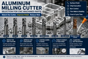
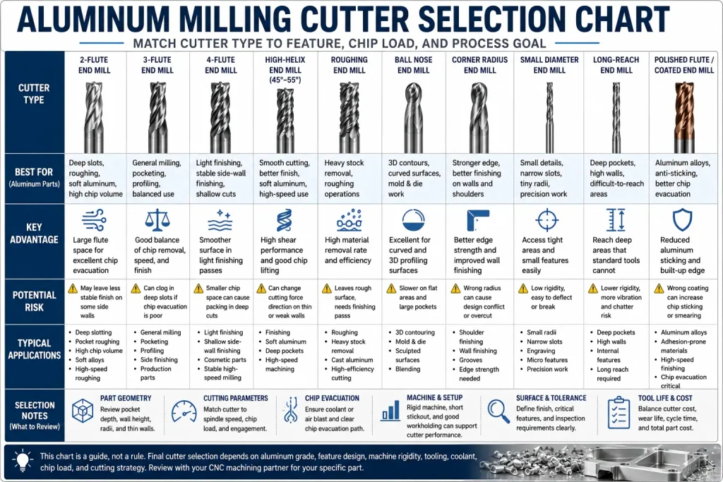
Quick Aluminum Milling Cutter Selection Chart
This chart gives a practical starting point.
| Cutter Type | Usually Better For | Main Risk |
|---|---|---|
| 2-flute end mill | Deep slots, roughing, softer aluminum, high chip volume | May leave less stable finish on some side walls |
| 3-flute end mill | General aluminum milling, balanced speed and finish | Needs good chip evacuation and correct feed |
| 4-flute end mill | Light finishing and stable side-wall finishing | Can clog in deep slots if chip space is too small |
| High-helix cutter | Smooth cutting action, better finish, softer aluminum | Can pull thin walls if setup is weak |
| Roughing cutter | Heavy stock removal | May leave rougher surface for finishing |
| Ball nose cutter | 3D contours and curved surfaces | Slower on flat areas |
| Corner radius end mill | Stronger edge, better finishing on selected features | Corner radius must match part design |
| Small diameter cutter | Small corners, narrow slots, small features | Deflection, breakage, and chatter risk |
| Long-reach cutter | Deep pockets and tall walls | Lower rigidity and more vibration |
| Polished flute cutter | Aluminum chip evacuation and anti-sticking performance | Still needs correct chip load and setup |
| Coated aluminum cutter | Selected production use, wear or anti-sticking support | Wrong coating can increase chip sticking |
This chart should not be treated as a fixed rule. Final cutter selection depends on material grade, feature geometry, machine rigidity, coolant, chip evacuation, tolerance, and surface requirement.
2-Flute Cutters for Aluminum
A 2-flute aluminum milling cutter has fewer cutting edges and more open flute space.
This is useful when chip evacuation is the main concern.
2-flute cutters are often reviewed for:
- deep slotting
- pocket roughing
- high chip volume cuts
- soft aluminum
- small machines with limited chip control
- parts where chip packing is a risk
- deep cuts where chips need more room to escape
The advantage is simple:
More flute space helps chips leave the cutting zone.
The risk is that fewer flutes may reduce finishing stability in some conditions. A 2-flute cutter can remove aluminum efficiently, but the final surface may still need a controlled finishing pass.
A 2-flute cutter may be a good roughing choice, but not always the best final finishing choice.
3-Flute Cutters for Aluminum
A 3-flute cutter is often a strong general-purpose choice for aluminum CNC machining.
It gives a balance between:
- chip evacuation
- cutting speed
- tool strength
- feed rate
- surface finish
- productivity
For many CNC aluminum parts, 3-flute polished carbide end mills are commonly reviewed because they can run faster than 2-flute tools while still leaving enough flute space for aluminum chips.
3-flute cutters are often used for:
- general milling
- pocketing
- profiling
- side finishing
- moderate slotting
- production aluminum parts
- cosmetic aluminum parts before finishing
- balanced roughing and finishing strategies
But 3-flute does not automatically solve everything.
If the slot is deep, the tool stickout is long, the coolant is poor, or chip packing occurs, a 3-flute cutter can still clog or create built-up edge.
The cutter must match the toolpath and chip evacuation plan.
4-Flute Cutters for Aluminum
A 4-flute cutter can work in aluminum, but it should be reviewed carefully.
More flutes can help with a smoother side-wall finish during light finishing cuts, but the smaller chip space can become a problem in deep slots, heavy roughing, or gummy aluminum.
4-flute cutters may be considered for:
- light finishing
- shallow side-wall finishing
- stable high-speed machining
- selected hard aluminum alloys
- low chip-load finishing passes
- parts where surface texture matters more than chip volume
They may be risky for:
- deep slotting
- gummy aluminum
- poor coolant flow
- heavy roughing
- long tool stickout
- small machines with weak chip evacuation
The buyer does not need to write “use 4-flute cutter” on the drawing unless there is a special reason.
It is usually better to define the required surface finish, tolerance, burr condition, and visible face. The CNC shop can then select the cutter that supports those requirements.
Cutter Material: Carbide, HSS, and Special Tools
Most production aluminum milling uses carbide cutters because carbide provides stiffness, wear resistance, and better high-speed stability.
| Cutter Material | Practical Use |
|---|---|
| Carbide | Most CNC aluminum production, finishing, high-speed milling, repeat work |
| HSS | Light-duty work, manual machining, low-speed use, simple prototypes |
| PCD / diamond tooling | High-volume production, abrasive aluminum alloys, selected non-ferrous applications |
| Special form cutters | Custom radii, grooves, chamfers, or profile features |
Carbide is not automatically perfect, but it is usually the practical baseline for CNC aluminum milling.
For very high-volume production, tool life may matter more than tool price. A more expensive cutter can reduce burrs, downtime, tool changes, and rework.
For one prototype, the shop may choose a practical cutter already available if it still meets the drawing requirement.
Coating Choice for Aluminum Cutters
Tool coating is important, but the wrong coating can make aluminum problems worse.
Aluminum often needs a cutter surface that reduces sticking and supports chip evacuation.
Common cutter options include:
| Cutter Surface | Practical Meaning |
|---|---|
| Polished uncoated carbide | Often good for aluminum because chips slide more easily |
| ZrN coating | Sometimes used for aluminum and non-ferrous materials |
| DLC coating | Can help reduce sticking in selected applications |
| TiAlN / steel-focused coatings | May not be ideal for aluminum if chip welding increases |
| PCD cutting edge | Used for selected high-volume or abrasive aluminum work |
Aluminum sticking is not only a mechanical friction problem. Under high pressure and cutting heat, aluminum can adhere to the cutting edge and form built-up edge, especially when chip evacuation, edge sharpness, coating choice, or lubrication is not well controlled.
Polished flutes can help chips slide away from the cutting zone, while aluminum-friendly coatings such as DLC or ZrN may help reduce adhesion in selected applications. However, coating choice should still be reviewed with the aluminum grade, cutting speed, coolant or air blast, tool geometry, and production quantity.
A more advanced coating does not automatically create a better aluminum finish. The cutter surface must support clean shearing, stable chip evacuation, and predictable tool wear for the specific part.
The key is not “coated or uncoated.”
The key is whether the cutter edge, flute polish, coating, and chip evacuation support clean aluminum cutting.
If the coating increases aluminum sticking, the finish may become worse even if the cutter looks more advanced.
Tool Geometry Matters More Than Buyers Expect
Flute count is only one part of cutter selection.
Tool geometry also includes:
- helix angle
- rake angle
- edge sharpness
- flute polish
- core diameter
- cutter diameter
- corner radius
- neck relief
- cutting length
- tool stickout
- runout control
- balance at high RPM
At the elevated spindle speeds often used in aluminum milling, cutter and toolholder condition becomes more important. Small tool runout, poor clamping, or imbalance can make one flute cut more than the others.
This uneven chip load can create vibration, micro-chatter, uneven tool wear, and visible finish variation on cosmetic or tolerance-sensitive aluminum surfaces. For parts with strict appearance, bore, wall, or flatness requirements, the supplier may review toolholder quality, collet condition, tool stickout, runout control, and balanced tooling for high-speed finishing.
The goal is not to require special holders for every aluminum part. The goal is to avoid treating a high-speed finishing cut as only a cutter selection issue.
For aluminum, a sharp cutting edge and polished flute are often very important.
A dull or poorly polished cutter can rub and smear aluminum instead of cutting cleanly.
This is especially important for:
- cosmetic parts
- thin walls
- fine finishing passes
- anodized visible parts
- small pockets
- burr-sensitive edges
- soft aluminum alloys
- high-speed machining
A good aluminum milling cutter should help the chip leave the cut. If the chip stays near the edge, the tool may re-cut chips and damage the surface.
Cutter Diameter and Internal Corner Radius
The cutter diameter controls what internal corner radius can be machined.
A common drawing mistake is designing a sharp internal corner or a very small radius without considering the cutter.
For example:
| Design Feature | Cutter Concern |
|---|---|
| Small internal corner | Requires smaller cutter |
| Deep pocket with small corner radius | Small cutter may need long reach, increasing chatter |
| Narrow slot | Cutter diameter and chip evacuation become critical |
| Thin rib between pockets | Cutting force may bend or vibrate the rib |
| Small bottom radius | May require ball nose or corner-radius cutter |
| High wall with small corner | Tool deflection and finish variation increase |
A smaller cutter can reach smaller details, but it is usually weaker.
Small cutters may have:
- lower rigidity
- higher breakage risk
- more deflection
- slower feed
- longer machining time
- more chatter risk
- harder chip evacuation
A design with slightly larger internal radii can often reduce machining risk and cost.
For drawing-level design review, see our CNC machining design guide.
Long-Reach Cutters and Deep Pockets
Deep pockets often force the shop to use longer tools.
A long-reach cutter has less rigidity than a short cutter. This can create:
- chatter
- tapered walls
- poor finish
- dimensional variation
- tool deflection
- slower cutting
- higher burr risk
- reduced tool life
The problem is not only depth. It is depth combined with cutter diameter, pocket width, corner radius, wall thickness, and material behavior.
A deep pocket with a large radius may be manageable. A deep pocket with a tiny internal corner may require a small long-reach cutter, which increases risk.
For RFQs, buyers should clearly mark:
- pocket depth
- corner radius
- required wall finish
- tolerance on pocket walls
- whether tool marks are acceptable
- whether the pocket is visible or functional
- whether the bottom surface needs a controlled finish
The cutter selection is part of the manufacturability review, not only a tool choice.
Thin-Wall Aluminum Parts Need Controlled Cutter Strategy
Thin-wall aluminum parts are sensitive to cutter force.
A cutter can push, pull, vibrate, or heat the wall during machining.
Thin walls may move because of:
- cutting force
- clamping force
- tool engagement
- heat
- residual stress release
- poor roughing sequence
- aggressive finishing passes
- long tool stickout
- weak support near the wall
For thin-wall aluminum, cutter selection should review:
| Item | Why It Matters |
|---|---|
| Sharp edge | Reduces cutting force |
| Cutter diameter | Affects stiffness and access |
| Flute count | Affects chip evacuation and force balance |
| Helix angle | Can affect pulling force on the wall |
| Radial engagement | Controls side pressure |
| Finishing allowance | Helps stabilize final wall size |
| Tool runout | Can mark or push the wall unevenly |
| Final pass direction | Can affect burr direction and wall finish |
Tool geometry also interacts with local part stiffness. High-helix aluminum cutters can shear material cleanly and help lift chips out of pockets, but they can also change the direction of cutting force on thin or unsupported features.
If a thin vertical wall has weak support, long free height, or poor damping, the cutter may pull, vibrate, or deflect the wall during finishing. This can lead to wall thickness variation, chatter marks, or a final shape that changes after unclamping.
For thin-wall aluminum features, the supplier may review helix angle, radial engagement, axial depth of cut, finishing allowance, toolpath direction, support strategy, and lighter final passes before confirming the process.
A thin-wall part may need a different cutter and toolpath from a solid block part, even if both are made from 6061 aluminum.
For high-speed aluminum process planning, see our high-speed CNC aluminum cutting guide.
Cutter Selection and Surface Finish
The cutter can strongly affect the final surface finish.
Surface finish problems may come from:
- dull cutting edge
- poor flute polish
- chip re-cutting
- built-up edge
- tool runout
- poor tool balance
- wrong feed per tooth
- excessive stickout
- weak fixture
- chatter
- wrong toolpath direction
- worn finishing tool
A clean aluminum surface often needs more than a smooth cutter.
It needs a stable cutting process.
For visible aluminum parts, the RFQ should define:
- visible surfaces
- acceptable tool marks
- roughness target if needed
- anodizing or painting after machining
- burr-sensitive edges
- packaging requirement
- cosmetic inspection standard
A machined surface that looks acceptable before anodizing may look different after anodizing. Tool marks, scratches, and burrs can become more visible after finishing.
For finish planning, see our CNC surface finishes guide.
Cutter Selection and Burr Control
Burrs are one of the most common quality problems in aluminum milling.
A cutter may create more burrs when:
- the edge is dull
- feed is too low
- chip load is unstable
- tool runout is high
- the part wall is thin
- the exit edge is unsupported
- the cutter rubs instead of cuts
- chip evacuation is poor
- the final pass direction pushes burrs toward a critical edge
Burr control is not only a deburring problem. It is also a cutter and toolpath problem.
For burr-sensitive parts, the drawing should mark:
- edges that must be burr-free
- edges that can have normal break edge
- cosmetic edges
- sealing edges
- threaded holes
- cross-hole intersections
- user-contact surfaces
- areas that cannot be over-rounded
A better RFQ note is:
Burr-sensitive edges marked on drawing. Supplier to review cutter direction, deburring access, and final edge inspection before production.
For edge quality planning, see What Is Deburring? CNC Edge Quality, Burr Removal, and Inspection.
Aluminum Grade Changes Cutter Behavior
Different aluminum alloys do not machine exactly the same.
| Aluminum Material | Cutter Selection Concern |
|---|---|
| 6061-T6 | Usually machines well; cutter choice focuses on finish, burrs, and productivity |
| 7075-T6 | Stronger material; tool wear, heat, and finishing stability need review |
| 5052 | Softer and more ductile; burrs and smearing can be more difficult |
| 6063 | Often used for extrusions; surface quality and cosmetic finish may matter |
| Cast aluminum | Porosity, silicon content, and variable structure may affect tool wear |
| Hard-anodized aluminum after machining | Pre-finish dimensions and masking must be reviewed |
| Thin extruded aluminum features | Clamping and wall movement may matter more than cutting speed |
For material comparison, review our 6061 vs 7075 aluminum CNC machining guide.
Cutter selection should not be copied from one aluminum alloy to another without review.
A setup that cuts 6061 cleanly may create burrs or tool wear problems in another grade or stock form.
Cutter Choice and Cutting Speed Work Together
A good aluminum milling cutter can still fail if the cutting speed, feed rate, and chip load are wrong.
The cutter must work with:
- spindle speed
- feed rate
- feed per tooth
- radial depth of cut
- axial depth of cut
- coolant or air blast
- machine rigidity
- fixture stability
- tool stickout
- chip evacuation path
If feed per tooth is too low, the cutter may rub instead of cut.
If feed is too high for the setup, the cutter may chatter, break, or leave poor finish.
If RPM is high but chip evacuation is weak, aluminum may weld to the cutting edge.
This is why cutter selection and cutting parameters should be reviewed together.
For parameter planning, see our cutting speed aluminum milling guide.
Tool Wear and Cutter Replacement Matter in Production
A cutter may work well at the start of production and then slowly create problems as it wears.
Tool wear can cause:
- larger burrs
- dull surface
- poor wall finish
- size drift
- higher heat
- more chatter
- chip welding
- inconsistent holes or pockets
- more deburring time
- more rejected cosmetic parts
In production, the question is not only which cutter is selected. The supplier also needs a plan for tool life and cutter replacement.
Important production checks include:
| Check | Why It Matters |
|---|---|
| Tool wear limit | Prevents running a dull tool too long |
| First article inspection | Confirms process before full batch |
| In-process checks | Catches dimensional drift |
| Burr monitoring | Shows when cutter edge is degrading |
| Surface finish check | Helps protect cosmetic or functional faces |
| Tool change interval | Supports repeatability across the batch |
| Batch documentation | Helps repeat the same result later |
For more detail, see our tool wear in aluminum machining guide.
Climb Milling, Conventional Milling, and Cutter Exit Direction
The same cutter can create different burrs and surface finish depending on cutting direction.
Climb milling and conventional milling change chip thickness, cutting force direction, burr direction, and surface behavior.
For aluminum, climb milling is often useful on stable CNC machines, but it is not automatic.
The process should review:
- cutter sharpness
- fixture rigidity
- backlash control
- thin wall support
- chip evacuation
- burr direction
- finishing pass direction
- surface finish requirement
- whether the cutter exits into a critical edge
If the cutter exit pushes material toward a sealing edge or visible edge, the part may need extra deburring or a different finishing path.
For cutting direction strategy, see our climb milling vs conventional milling guide.
When Buyers Should Not Specify the Cutter
Most buyers should not over-specify the exact cutter unless there is a functional reason.
Avoid writing detailed cutter requirements when:
- the cutter brand is not important
- the part only needs standard machining
- the supplier can meet the drawing with normal tooling
- the buyer does not understand the process limit
- the cutter note may block a better manufacturing method
- the requirement is copied from another supplier without review
Instead of writing:
Use 3-flute polished carbide end mill
A safer note may be:
Visible face requires clean machined finish. Burrs on marked edges not acceptable. Supplier to review cutter, toolpath, and deburring method.
This gives the supplier freedom to choose the right cutter while keeping the quality requirement clear.
Buyers should specify the result, not force the tool, unless the tool choice is part of a validated process.
When Cutter Requirements Should Be Discussed Before Quoting
Cutter selection should be discussed when the part has:
- thin walls
- deep pockets
- narrow slots
- small corner radii
- tight tolerance surfaces
- visible cosmetic faces
- high burr sensitivity
- anodizing after machining
- high-volume production
- long continuous cutting time
- special surface finish needs
- difficult chip evacuation
- expensive material or high scrap cost
- high-speed machining requirement
In these cases, cutter selection affects cost, risk, and delivery.
A good RFQ does not need to tell the supplier every cutter detail. But it should give enough information for the supplier to select the cutter properly.
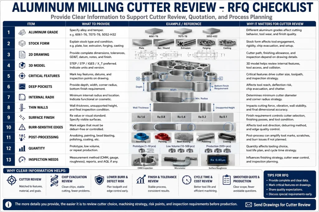
RFQ Checklist for Aluminum Milling Cutter Review
Before quoting aluminum CNC milled parts, send clear information about the features that affect cutter selection.
| RFQ Item | What to Provide |
|---|---|
| Aluminum grade | 6061, 7075, 5052, 6063, cast aluminum, or other grade |
| Stock form | Plate, bar, extrusion, forging, casting, or billet |
| 2D drawing | Dimensions, tolerances, surface finish, datum notes |
| 3D model | STEP / STP / IGES / X_T if available |
| Critical features | Bores, slots, thin walls, pockets, datum faces, visible faces |
| Deep pockets | Depth, wall height, corner radius, bottom finish |
| Internal radii | Minimum radius and whether it is functional or cosmetic |
| Thin walls | Wall thickness, unsupported height, final inspection condition |
| Surface finish | Ra target, cosmetic expectation, visible surfaces |
| Burr-sensitive edges | Mark edges that cannot have raised burrs |
| Post-processing | Anodizing, painting, bead blasting, polishing, or coating |
| Quantity | Prototype, low volume, or repeat production |
| Inspection needs | CMM, gauges, surface roughness, visual standard, or report |
| Delivery target | Helps plan tooling, setup, and production route |
The supplier can use this information to review cutter diameter, flute count, tool reach, finishing passes, chip evacuation, and inspection risk.
Practical Drawing Notes for Aluminum Milling Cutter Risk
Example 1: Thin Wall
Thin wall area marked on drawing. Supplier to review cutter engagement, clamping, and final finishing pass before production.
This helps prevent wall movement and chatter.
Example 2: Cosmetic Face
Visible surface requires clean machined finish. Tool marks acceptable only within approved sample or agreed visual standard.
This prevents confusion between functional machining and cosmetic acceptance.
Example 3: Small Internal Radius
Minimum internal radius shown is functional. Supplier to confirm cutter access and machining risk before quotation.
This helps avoid using a weak small cutter without review.
Example 4: Burr-Sensitive Edge
Marked edges must be free of raised burrs after machining and deburring. Do not over-round sealing edge.
This protects function while allowing controlled deburring.
Example 5: Post-Anodizing Surface
Visible machined surfaces will be anodized after machining. Supplier to review pre-anodizing tool marks, burrs, and masking needs.
This avoids cosmetic surprises after finishing.
Common Aluminum Milling Cutter Mistakes
Many aluminum milling problems come from small tooling mistakes.
Common mistakes include:
- using a steel-focused cutter on aluminum
- choosing too many flutes for deep slotting
- using a dull tool to finish visible surfaces
- using too much tool stickout
- ignoring tool runout
- using a cutter too small for a deep pocket
- designing tiny internal radii without reason
- using low feed until the cutter rubs
- re-cutting chips in pockets
- not marking burr-sensitive edges
- polishing or anodizing over poor tool marks
- not replacing tools during repeat production
- assuming one cutter works for every aluminum grade
For buyers, the safest approach is simple:
Define the part function, surface requirement, burr condition, tolerance, and final finish. Let the supplier review the cutter and process needed to meet those requirements.
Rapid Efficient Support for Aluminum Milling Cutter Review
Rapid Efficient can review aluminum CNC milled parts before quotation and help identify whether cutter selection may affect part quality.
We can review:
- aluminum grade
- part geometry
- thin walls
- deep pockets
- small internal radii
- burr-sensitive edges
- visible surfaces
- surface finish requirement
- anodizing or coating after machining
- tolerance and inspection needs
- prototype or production quantity
- packaging requirement
Depending on the part, cutter selection may involve 2-flute, 3-flute, high-helix, polished flute, corner-radius, long-reach, or finishing cutters.
For aluminum part production support, see our CNC aluminum machining services page.
Send us your STEP file, 2D drawing, aluminum grade, critical features, finish requirement, quantity, and inspection needs.
Buyer Questions About Aluminum Milling Cutters
What cutter is best for aluminum milling?
There is no single best cutter for every aluminum part. 2-flute cutters often help with chip evacuation, 3-flute cutters are common for balanced aluminum milling, and 4-flute cutters may be used for light finishing. The best choice depends on feature geometry, chip removal, machine rigidity, and surface requirement.
Is a 2-flute or 3-flute cutter better for aluminum?
A 2-flute cutter gives more chip space and can help with deep slots. A 3-flute cutter often gives a good balance of speed, finish, and chip evacuation. The feature and toolpath matter more than the flute count alone.
Can I use a 4-flute end mill for aluminum?
Yes, in some light finishing conditions. But 4-flute cutters can trap chips more easily in deep slots or heavy roughing, so chip evacuation must be reviewed.
Should aluminum cutters be coated?
Sometimes. Polished uncoated carbide, ZrN, DLC, or other aluminum-friendly options may work depending on the part. The wrong coating can increase chip sticking, so coating should be selected for aluminum behavior, not just wear resistance.
Why do aluminum cutters create burrs?
Burrs can come from dull edges, low chip load, poor chip evacuation, tool runout, weak support, or cutter exit direction. Burr control should be planned before machining, not only after machining.
Does cutter choice affect anodized aluminum appearance?
Yes. Tool marks, burrs, scratches, and uneven surface texture before anodizing can remain visible or become more noticeable after anodizing. Visible surfaces should be marked clearly before quotation.
What should I send for aluminum milling cutter review?
Send a 2D drawing, 3D model, aluminum grade, critical features, pocket depth, minimum internal radius, thin-wall areas, surface finish requirement, burr-sensitive edges, post-processing requirement, quantity, and inspection needs.