A plastic guide can show little wear and still move a component out of position. Its contact face may compress, its mounting holes may change shape, or a long strip may bow as the machine warms up.
That is the main issue in Delrin vs UHMW selection: the plastic must keep the required shape while doing its sliding or wear job.
Delrin is often the better starting point for compact parts that need stiffness, well-defined features, and controlled movement under load. UHMW is often attractive for supported wear strips, liners, and impact-prone sliding surfaces. Both can work in bearings, guides, and other moving parts. The final choice depends on the grade, contact geometry, support, temperature, and mating surface.
Delrin is a brand of acetal homopolymer, also called POM-H. UHMW means ultra-high molecular weight polyethylene, commonly written UHMW-PE or PE-UHMW. It is a different polymer from acetal and should not be substituted with ordinary HDPE without review. A drawing that requires Delrin should also distinguish it from acetal copolymer, POM-C. Our Delrin CNC machining guide explains the stock and machining implications of that distinction.
Compare the Plastic at the Loaded Contact
Start with the surface that carries the load. Then identify the structure behind it and the movement the assembly can accept.
The following table gives starting directions for standard, unfilled engineering stock. Modified grades can change the comparison.
| Contact and support | Movement that matters | Starting direction | Detail that can change the choice |
|---|---|---|---|
| Small locating pad or compact guide block | Compression changes the location of the supported part | Review Delrin first when stiffness and feature accuracy dominate | Actual contact area, sustained load, and allowable displacement |
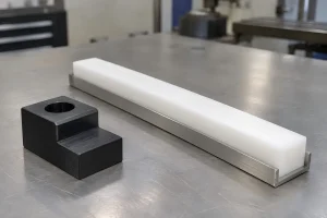
| Long sliding strip backed by a metal rail | Local indentation, wear loss, and lengthwise thermal movement | Review UHMW when sliding wear and impact resistance dominate | Backing continuity, expansion space, and retention design |
| Gear tooth, small boss, or narrow unsupported feature | Bending changes engagement or alignment | Delrin often provides a more practical starting point | Tooth or feature geometry, cyclic load, temperature, and grade |
| Bushing carrying a shaft | Loaded clearance, contact temperature, and wear | Either material may be suitable after application review | Wall support, pressure, speed, lubrication, and shaft condition |
| Sliding face that must also locate a component accurately | Wear and deformation both alter position | Consider a supported wear layer with a separate locating structure | How the carrier, plastic thickness, and replacement method affect location |
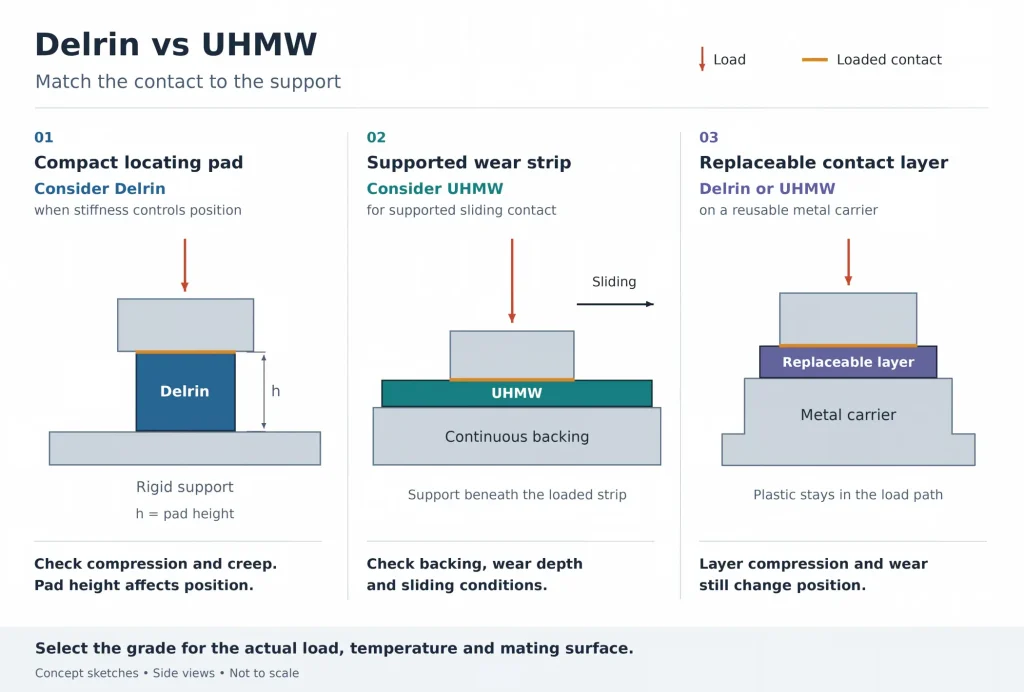
Support can change the material choice as much as the material name.
A broad UHMW strip on a rigid backing has a different job from a narrow UHMW finger extending beyond its support. Likewise, a Delrin block can provide useful stiffness while still wearing, creeping, or moving with temperature.
Contact Area Changes Both Pressure and Position
For a nominally flat contact, average pressure is calculated as:
Here, is the normal force and is the contact area carrying that load.
For example, a 200 N load spread over 500 mm² produces an average pressure of 0.4 MPa. If that same load acts on only 20 mm², the average pressure rises to 10 MPa.
These values illustrate the effect of contact area; they are not allowable stresses for either plastic. Edge contact, shaft contact, and local surface errors require a more suitable contact analysis.
This matters when a nominally large pad actually touches at one corner, or when a roller loads only a narrow region of a wear strip. The plastic may move enough to change alignment before it shows serious wear.
Separate initial deflection from long-term movement
Stiffness controls the initial response to load. Creep is the additional deformation that develops over time under a sustained load. Stress relaxation is the reduction in stress when a plastic feature is held at a fixed deformation.
In a press fit or compressed retaining feature, stress relaxation can reduce contact pressure and holding force over time even if the assembly position stays fixed. These distinctions are explained in Delrin’s creep and stress relaxation guide.
For both materials, review the expected load, temperature, service time, and acceptable movement. A short-term tensile modulus or yield value does not establish long-term positioning performance.
Useful design changes may include increasing the bearing area, moving support closer to the loaded contact, or transferring a fastener’s clamp load through a suitable metal spacer. The spacer and fastener must still hold the part securely while allowing any intended thermal movement.
Long UHMW Strips Need Room to Move
Low moisture uptake makes UHMW useful in many wet environments. It still expands with temperature, and a long strip can accumulate enough growth to affect guide spacing or mounting.
For example, the TIVAR 1000 Virgin UHMW-PE datasheet lists a linear thermal expansion coefficient of 200 µm/(m·K) over 23–100°C. This is indicative data for that grade, not a value to assign to every UHMW product.
Using that coefficient for a simple estimate, consider a 500 mm strip warming from 25°C to 55°C:
This is calculated free expansion. In an assembly, the carrier also moves. If both components undergo the same uniform temperature change, their approximate relative movement is:
Use the actual materials and temperatures when setting gaps and slot travel. For each gap or slot, measure the reference length from the fixed location to that feature. Delrin also requires thermal allowance; choosing the stiffer plastic does not remove this calculation.
Define the fixed location and the movement path
A long strip needs a clear locating strategy. One mounting option fixes the strip at a defined location and lets it move lengthwise at the other retaining points. Other designs use retaining channels or segmented strips, with mounting details suited to the load.
Röchling’s assembly guidance for UHMW-PE dewatering elements illustrates this principle with retaining profiles and elongated mounting holes. Set the support spacing, gaps, and slot travel for the actual strip geometry, load, material grade, and temperature range.
For a proposed mounting arrangement, check:
- Where the strip is fixed, and which direction each section can move.
- Whether the retaining hardware actually permits movement along a slot.
- Whether the backing supports the loaded area between attachments.
- Whether gaps remain acceptable at both hot and cold conditions.
- Whether fastener heads remain below the contact surface through the permitted wear depth.
- Whether the strip stays retained as it contracts.
Countersunk screw heads can concentrate stress in UHMW and lock a mounting point that needs to slide. A flat bearing face, washer, shoulder screw, or spacer can help manage the load, but the detail must still allow movement where required. Curbell’s plastic part design guidance explains the stress risks around tapered fastener heads.
A slot alone does not provide free movement if the fastener clamps the plastic firmly to the carrier. The same applies to a counterbore and washer. Check the remaining plastic thickness and fastener clearance through the permitted wear depth. The retention detail must control lift and lateral movement while allowing the intended thermal travel.
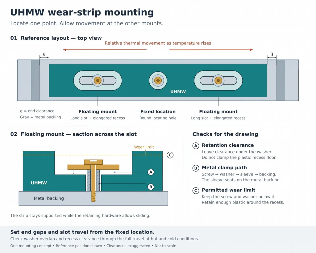
If the assembly blocks expansion, the response may include compressive stress, creep, or bowing. Leaving an uncontrolled gap can create a different problem, such as a step or snag point in the sliding path.
Compare Wear Against the Actual Mating Surface
Both UHMW and Delrin are used in sliding parts. Wear-modified grades can change their performance.
Compare tests using relevant mating materials, finishes, loads, speeds, and lubrication. Slurry abrasion data does not predict dry shaft-bearing life, and friction values from different counterfaces are not directly comparable.
The counterface is the surface rubbing against the plastic. Its roughness, hardness, damage, and contamination can change the result.
For dry-running bushings, check PV = p × v, where p is the specified bearing pressure and v is sliding speed. Use the pressure definition, units, and test conditions supplied with the grade data. Check the separate pressure and speed limits as well. Lubrication, duty cycle, and heat removal affect the result; equal PV values can still produce different wear. Melting point does not set a safe operating temperature. Delrin’s low-wear and low-friction guide explains how the working conditions affect performance.
For the actual part, define the functional wear limit. Examples include a loss of guide thickness that changes product position, extra bushing clearance, or a wear step that catches a moving edge.
In a simplified example, allow a total surface shift of 0.10 mm. Assume all position changes other than wear use 0.06 mm in the same direction. That leaves 0.04 mm for wear, even if the strip itself is 5 mm thick. These assumed values illustrate a wear allowance; they do not predict service life.
Then test the proposed grade against the intended mating surface under representative conditions. Include starts, stops, dwell under load, and debris when they are part of service. A continuously running test may miss a problem that appears after a loaded stop.
The useful result is acceptable friction, temperature, geometry, and wear together.
A Supported Wear Layer Can Change the Choice
Some parts ask one plastic to perform two jobs: hold a precise location and provide a replaceable sliding surface.
Consider separating those functions where the assembly allows it. A metal carrier can establish mounting geometry and provide backing, while a Delrin or UHMW element supplies the contact surface.
This does not remove the plastic from the tolerance calculation. If a component rests on the wear layer, compression and wear of that layer still change its position. The design must account for initial thickness, supported deformation, permitted wear, and the method used to restore the surface after replacement.
This approach can be useful when:
- The carrier is expensive to replace but the contact face is a wear item.
- A long guide needs continuous support and controlled thermal movement.
- Different contact grades must be evaluated without rebuilding the whole mount.
- Replacement thickness or adjustment can restore the required location.
It also changes the cost comparison. Review stock yield, machining, carrier hardware, replacement access, and the parts that must be discarded together. The lowest material price alone does not identify the lowest-cost assembly.
CNC Details That Can Change the Result
Delrin generally suits well-defined machined features. UHMW bends and compresses more readily, which calls for particular care with unsupported walls, narrow sections, and inspection force. Both materials can be distorted by workholding or local heat.
For a long UHMW guide, the drawing should distinguish the loaded contact face from nonfunctional outer surfaces. The machining plan should support the strip without forcing it into a shape that disappears when the clamps are released.
For a Delrin locating block, the important features may be a bore, shoulder, pad height, or hole pattern. Their relationship after unclamping matters more than an attractive surface on a nonfunctional face.
Three details deserve review:
Cutting and edge condition. Sharp tools and effective chip removal help limit rubbing and heat. Select cutting speed and feed together for the tool, material grade, and part support. Inspect for stringy burrs or stretched edges, especially where a small lip could scrape the mating part. Define any edge break so manual cleanup does not alter the working contact.
Fasteners and small features. Review direct plastic threads, narrow retaining lips, and deeply recessed fasteners against the actual loads. Where inserts or through-fasteners are used, check the surrounding wall and the load path through the assembly.
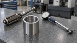
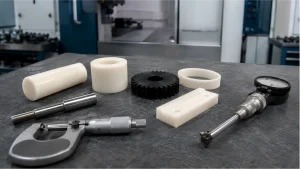
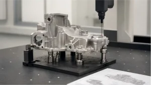
Acceptance measurements. Specify temperature, support, and restraint. Use a measurement method and contact force appropriate to the feature. A soft contact face can move under a probe or gauge, and a long strip can change shape when laid on different supports.
The CNC machining tolerances guide provides broader drawing guidance. For this comparison, the essential requirement is the final functional geometry in the agreed inspection and assembly state.
Check the Service Environment Before Fixing the Grade
Moisture response is only one part of environmental suitability. UHMW’s low moisture uptake does not establish suitability for every cleaning chemical, temperature, or washdown cycle under load. Delrin also needs grade-specific review where hot water, aggressive cleaning, or extended chemical exposure is involved.
State the chemical, concentration, contact time, and temperature. If cleaning occurs while the part is loaded or restrained, include that condition in the review. Distinguish a short cleaning cycle from continuous exposure.
For outdoor use, static-sensitive handling, or food contact, request the appropriate grade and documentation. Color alone does not establish UV resistance, electrical behavior, or regulatory suitability. Filled and modified grades also require their own mechanical and wear review.
If humidity-driven swelling is the main alternative-material concern, the Delrin vs Nylon comparison addresses that decision. If neither Delrin nor UHMW can meet the required load, temperature, or dimensional stability, use the best plastics for CNC machining guide to widen the shortlist.
Send the Contact and Mounting Details With the Part Drawing
A useful Delrin–UHMW quotation needs the assembly details that determine material choice.
Along with the part drawing, identify the loaded contact area, backing surface, mating material, direction of movement, load duration, speed, and temperature range. For a wear strip, include the fixed location, retention details, expansion space, and permitted wear depth. For a locating part, identify the position or clearance that must remain within limits under load.
State the requested grade and stock form, or clearly allow a proposed alternative. Define the acceptance condition and any representative wear or assembly test needed before a production order.
Rapid Efficient can review these details alongside machining and inspection requirements through our CNC machining services. The review can compare a one-piece plastic component with a supported, replaceable contact element where either approach suits the assembly.