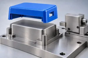
A snap hook, retaining groove, or side hole can keep a molded part trapped on the steel that formed it. Choosing the release method early helps preserve the feature without creating unnecessary tooling complexity.
An undercut in injection molding is a feature that blocks direct removal along a chosen mold-opening or ejection direction. Depending on the geometry, it may be resolved by changing the part orientation, modifying the feature, moving a mold component, or allowing controlled deformation during release.
Start by identifying which surface causes the obstruction and what that surface must do in the finished assembly.
Start with the Direction the Mold Must Open
Undercuts depend on the proposed pull direction. A hole that requires a side core in one orientation may align with the main opening direction in another.
Review the complete part after any reorientation. Freeing one feature can trap another, move the parting line onto a visible surface, or make ejection more difficult. Protolabs describes this orientation check in its undercut design guidance.
In the CAD review, identify the main opening direction and trace how each piece of forming steel will leave the plastic. Check the full withdrawal path, including nearby ribs and walls.
Draft helps surfaces separate along that path. Adding draft to adjacent walls does not remove an unchanged retaining shoulder that still blocks withdrawal.
If the feature will instead be cut after molding, the undercut machining guide addresses cutter access, tool clearance, and inspection access.
Remove the Obstruction Without Losing the Feature
Before selecting a moving core, check whether the product can accept a change that allows the two main mold halves to form and release the feature.
Useful options include:
- Moving a feature to the parting line so both mold halves can reach it.
- Opening a window beneath a hook so steel can form its retaining face through the opposite side.
- Replacing a closed side hole with an open slot when the assembly permits it.
A shutoff is a contact between mold surfaces that blocks resin from entering a particular region. Properly arranged shutoffs can form some holes and hooks without a separate side action.
For shutoff faces that slide past each other, review draft together with contact length, alignment, and steel support. The design should limit rubbing during opening and closing while maintaining the seal under molding loads. Wear or damage at that contact can produce flash. Protolabs’ shutoff examples illustrate this relationship between geometry, draft, and sealing.
The required angle depends on the shutoff arrangement and tooling requirements. A recommendation for one sliding contact should not become a universal angle for every shutoff surface.
The engineering tradeoff is the effect on the product. A window beneath a hook may be unacceptable in a sealed enclosure. An open slot may lose a pin-retention function. Moving a parting line may place flash where a mating component must slide.
Compare the revised feature with its assembly requirement before accepting the simpler tool.
Give Each Trapped Surface a Release Motion
When the undercut must remain, select a mechanism by its withdrawal path and available space.
| Trapped feature | Candidate release motion | What the tool review must confirm |
|---|---|---|
| Side hole or external recess | A slide or side core withdraws across the main opening direction | The core clears the feature before obstructed part movement; there is room for travel, guidance, and locking |
| Local internal hook | A conventional inclined lifter moves forward during ejection while its head shifts sideways | The combined motion clears the hook without hitting adjacent walls or distorting the part |
| Internal annular groove | A collapsible core reduces its outside profile before the part is stripped off | Sufficient collapse exists at the groove’s actual depth, with clearance for the entire withdrawal path |
| Internal screw thread | An unscrewing core rotates out; a collapsible core may be another option for suitable geometry | Thread form, release travel, part restraint, and acceptable tool-split marks suit the selected method |
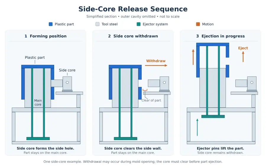
These are candidate routes. Their suitability depends on the complete feature and available space, rather than an internal or external label alone. Component manufacturers document several mechanisms with different motions and installation requirements.
For a conventional fixed-angle lifter whose displacement in the ejection direction equals the ejector plate stroke, the nominal relationship is:
Lateral travel = Effective ejector stroke × tan θ
Here, θ is the angle between the lifter’s travel direction and the ejection direction. The available lateral travel must clear the undercut with the required release allowance.
DME’s VectorForm design guide shows this relationship for a conventional arrangement and also describes installations that accelerate or decelerate lifter movement. Those arrangements require their actual motion relationship to be checked. Select the angle and stroke against the chosen components’ guidance, load, and travel limits.
Check the lifter head’s position relative to both the moving part and other mold components throughout the stroke. Include nearby ribs, bosses, and core inserts. Clearance at the final position alone does not prove that the intervening path is clear.
For a low-volume project, a removable hand-loaded insert may also deserve review. Its apparent tooling saving must be compared with loading, removal, handling consistency, and recurring labor.
At the injection mold tooling review, compare how each option affects mold space, cooling access, cavity layout, maintenance, and production quantity. There is no reliable universal percentage for the cost added by an undercut.
Check Radial Clearance Before Choosing a Collapsible Core
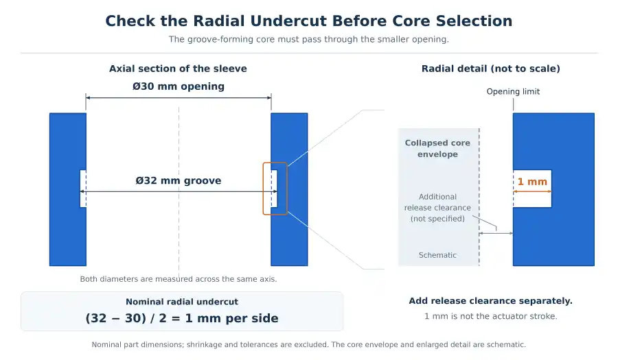
Consider a simplified rigid sleeve with an internal annular, or ring-shaped, groove:
- Smaller opening diameter: 30 mm
- Groove major diameter: 32 mm
Ignoring shrinkage and tolerances for this first geometric check, the radial obstruction is:
Radial undercut = (32 − 30) / 2 = 1 mm per side
The steel that forms the larger diameter cannot pass through the smaller opening while its outside profile remains unchanged.
That 1 mm is the nominal geometric obstruction. It is not the additional release clearance, a finished core specification, or the required axial actuator stroke. The selected mechanism must provide clearance at the feature’s location and account for dimensional variation and the part’s condition during release.
DME’s collapsible-core design guide treats undercut depth, available collapse at the feature location, shrinkage, and clearance as separate considerations. Use the component supplier’s calculation for the selected core; limits from one core design do not automatically apply to another.
Check the collapsed core along the full exit path, including any smaller opening beyond the groove.
Treat Bump-Offs as a Material and Geometry Decision
A bump-off releases a shallow undercut by temporarily deforming the plastic as it passes over the forming steel.
Its feasibility depends on the undercut profile, surrounding wall geometry, resin grade, and mold design. A smooth release ramp or radius can allow deformation that a sharp retaining hook prevents. Protolabs’ bump-off guidance explains these shape and material conditions.
For an engineering review, also ask:
- Where can the wall flex, and what limits that movement?
- What strain and force occur at the intended demolding temperature?
- How will ejection support the part without crushing or marking it?
- Does the retaining feature recover sufficiently to meet its assembly requirement?
Ejection contact area matters. Concentrating the release force on small contact areas can damage a locally weak or warm wall. For suitable ring-shaped or cap-like parts, a stripper ring, stripper plate, or ejector sleeve may distribute the load more effectively. The contact area and support still need to suit the actual part geometry, material, and ejection temperature.
A material family name alone cannot establish whether a feature can be bumped off. Changing the grade, reinforcement, wall thickness, or cooling condition can change the result.
Do not assume that a clip which flexes during assembly will survive the proposed molding release. The deflection direction, support, and temperature may be different.
Validate the released feature for cracking, whitening, permanent set, and required retention performance. Avoid a universal “safe undercut percentage” detached from the actual geometry and material.
Approve the Retaining Feature After Ejection
A part that leaves the mold still needs to meet its functional requirements.
For the drawing and sample review, identify the surfaces that establish hook engagement, groove retention, thread fit, sealing, or sliding contact. State where tool-split witness lines, mismatch, and flash are acceptable, and define limits where they could interfere with function.
A useful sample plan may include:
- Measuring hook engagement or groove dimensions from the relevant assembly datums.
- Checking critical contact surfaces for flash, steps, drag marks, and local damage.
- Testing insertion and retention with the specified mating component or agreed gauge.
- Recording the resin grade, cavity identity, and conditioning state when they affect the result.
Agree whether dimensions apply after a defined cooling or conditioning period, and whether flexible parts are measured free or restrained. A measurement made while the part is still warm may not represent its specified service condition.
The first article inspection guide explains how to connect drawing requirements with dimensional and functional evidence. Define the submission required for this molded part; a sample measurement report and a formal FAIR have different scopes.
Review the release approach and critical-surface requirements before mold manufacture so proposed geometry changes can be considered before steel is cut.
For an undercut review through Rapid Efficient’s injection molding services, share the CAD model with the trapped features marked, the intended resin grade, mating geometry, required retention or sealing function, and areas where openings or witness lines are restricted. Include the expected production quantity so the review can compare manual and automatic release options.
Rapid Efficient can review these requirements and coordinate the proposed tooling approach and sample checks before quotation.