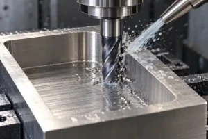
CNC machining fixtures must accommodate the dimensional variation in the parts they hold. A second-operation fixture needs to accept the output of the first operation, locate it consistently, and support it without changing the shape that matters after release.
Machined soft jaws may provide everything a job needs. Other parts require a fixture plate, separate locating pins, or supports beneath flexible sections. The choice depends on which surfaces are available when the part is loaded, where cutting forces act, and how the setup behaves when the next part arrives.
Start with the incoming workpiece and the loading sequence. Then check the locating clearances, clamping load path, and repeatability of the complete setup.
Choose the Fixture Around the Incoming Part
The finished CAD model does not show every condition a fixture must accommodate. A casting may arrive with draft and surface variation. A sawn blank may have inconsistent edges. A partially machined housing may have accurate locating holes but still carry stock on its outer walls.
Identify which features actually exist before each operation. Record which are machined, which remain rough, and which must survive until the next setup.
Locators establish position. Supports carry the workpiece and resist loads. Clamps keep the part seated against those contacts. One component can perform more than one function, but the fixture design should make each function clear. Our CNC machining datums guide explains how setup references relate to the drawing.
| Fixture approach | When it suits the job | What to check before committing |
|---|---|---|
| Standard vise with machined soft jaws | Parts with accessible gripping surfaces and a manageable loading orientation | Jaw engagement, lift during tightening, tool clearance, and distortion at the selected gripping force |
| Fixture plate with separate locators and clamps | Parts needing distributed support or access that a vise would obstruct | Locator clearances, clamp placement, chip removal, and the order of loading |
| Dedicated nest with selected contact areas | Irregular parts that need support at several defined regions | Incoming shape variation and whether the contacts allow every acceptable part to seat |
A nest should not automatically reproduce the entire nominal surface of the part. Multiple uncontrolled contact points can make seating depend on small variations in the workpiece. Selected contacts and relieved areas often provide a more predictable setup.
For soft jaws, the condition under which the jaws are machined matters too. Follow the vise manufacturer’s guidance for jaw preload and consider the intended gripping force. The jaw shape and contact can change under load.
Put Support Under the Clamping Load
A clamp can stop visible movement while bending the workpiece.
Consider a housing with a thin flange extending beyond the fixture support. Tightening a strap clamp over that extension bends the flange downward. Machining it in that condition may produce an acceptable measurement while clamped, followed by a different shape after release.
Place the clamping load over a support or a section stiff enough to carry it.
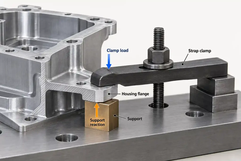
Trace the force from the clamp, through the part, and into the fixture. Also consider cutting forces that can lift, slide, or rotate the workpiece. Increasing clamp force is not a reliable correction for a poor support arrangement.
Adjustable work supports need similar care. Their initial contact should not jack the part away from its locators. After contact, the support must resist the loads expected during machining.
ROEMHELD’s work-support guidance distinguishes the force used to contact the workpiece from the load a locked support can carry. These are different design requirements. Set the contact, locking, and clamping sequence to suit the selected hardware and fixture layout.
Inspect the released part in the condition required by the drawing. A flexible component may need a specified restraint during inspection; another may require evaluation without clamping. Neither condition should be assumed from the machining setup alone.
Our thin-wall aluminum machining guide covers the additional effects of reduced stiffness and material removal. Fixture-induced bending and residual-stress movement can occur together, so a change after unclamping does not identify the cause by itself.
Two Tight Round Pins Can Prevent the Part from Seating
Two locating holes do not automatically call for two close-fitting round pins.
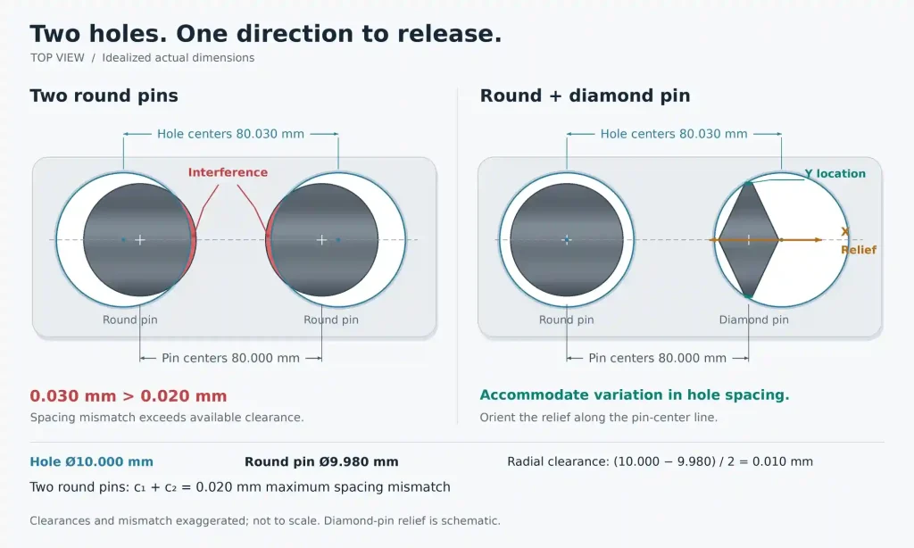
Once a part rests on its primary supports, a round pin can establish its in-plane location. A second round pin also restricts movement along the line joining the pins. If the hole spacing and pin spacing differ too much, the part will not seat freely.
Consider this idealized example. The values below represent assumed actual dimensions, rather than nominal drawing dimensions with unspecified tolerances.
| Quantity | Illustrative value |
|---|---|
| Diameter of each locating hole | 10.000 mm |
| Diameter of each round pin | 9.980 mm |
| Radial clearance at each pin | 0.010 mm |
| Distance between hole centers | 80.030 mm |
| Distance between pin centers | 80.000 mm |
| Spacing mismatch | 0.030 mm |
The radial clearance at each pin is:
(10.000 − 9.980) ÷ 2 = 0.010 mm
With the part free to shift in the plane, the two clearances can accommodate an ideal spacing mismatch of up to:
0.010 + 0.010 = 0.020 mm
The actual mismatch in this example is 0.030 mm. It exceeds the available accommodation, so the two round pins cannot enter both holes without deformation or interference.
This calculation assumes rigid parts, parallel axes, and circular features without form error. At the theoretical 0.020 mm limit, no additional assembly margin remains. A production design must account for dimensional limits, temperature, surface condition, and any other contacts that restrict movement.
A common solution is a round pin paired with a diamond pin. The diamond pin provides relief along the line between the pin centers while retaining locating contact across that line to control rotation. Carr Lane explains this division of constraints in its round-and-diamond locating arrangement.
Check the diamond pin’s orientation during fixture assembly. Its relieved direction should follow the line joining the pin centers, while the locating contact acts across that line to control rotation about the round pin. Specify and verify the orientation using the selected pin’s drawing and the fixture’s tolerance requirements.
The relief accommodates spacing variation; it does not remove all locating error. Pin clearance still contributes to the position the workpiece can occupy. Include that movement in the machining error budget.
Also distinguish a machining fixture from an inspection gauge. A fixture designed to accommodate incoming variation does not automatically verify that a hole pattern meets its drawing requirements.
Leave Room for Loading, Cutting, and Cleaning
Check three sets of movements before approving the layout:
- The path used to load and remove the workpiece.
- The movement of clamps and other actuated components.
- The travel of the cutting tool, holder, spindle, and any rotating machine axes.
A clamp may clear the programmed cutter while blocking its holder. A housing may fit once seated but have no practical loading path with the clamps open. These problems need the complete fixture geometry in the setup review.
Keep locating surfaces accessible for cleaning. A chip trapped beneath a support can change the part’s height or angle, even when the clamp sequence is repeatable. Relief pockets should provide somewhere for debris to go without creating inaccessible collection points.
Where incorrect loading is possible, use a visible orientation feature or a suitable mistake-proofing feature. It should prevent the wrong setup without forcing a correctly oriented part against unintended contacts.
Test Reloading Separately from Cutting
One successful part provides limited evidence about a fixture that will be loaded repeatedly.
Separate the main sources of variation during qualification. Otherwise, measurement scatter, seating changes, and machining effects become mixed together.
| Trial | Keep controlled | What to record |
|---|---|---|
| Measure the seated part repeatedly without unclamping | Part seating, reference alignment, and measurement method | Baseline measurement variation and drift |
| Unload, clean, and reload the same part | Part geometry and the intended loading sequence | Changes in location, angle, and seated height |
| Load representative parts from the preceding operation | Fixture settings and measurement method | Sensitivity to incoming dimensional and form variation |
| Remove and reinstall the fixture, if production requires it | Fixture mounting procedure and reference checks | Variation introduced at the machine-to-fixture interface |
| Machine representative parts and inspect after release | Agreed machining and inspection conditions | The combined effect of workholding, cutting, and release |
For a diagnostic reload test, retain a common reference alignment so that seating movement remains visible. Re-zeroing the measurement to each newly loaded part can hide the movement being investigated.
If production probing updates work offsets after loading, test that complete sequence separately. Probing may compensate for permitted rigid shifts. It cannot generally undo a workpiece that has been bent by the clamps.
Likewise, a repeatability specification for a zero-point mounting system applies to a particular interface and test condition. It does not establish the finished-part accuracy of the entire fixture, workpiece, tool, and machine system.
Set acceptance criteria from the part’s requirements and the error budget for the operation. Fixture variation must leave room for other contributors, including incoming feature variation, machining effects, and measurement uncertainty. There is no single reload tolerance or sample count suitable for every fixture.
Use the first article inspection guide to plan the dimensional evidence required for the initial part. Keep that evidence separate from the additional testing needed to understand repeat loading.
Compare Fixture Cost with the Work It Removes
A dedicated fixture can be justified for a small batch when the geometry or tolerance requires it. It can also add unnecessary expense where well-designed soft jaws would provide adequate access and support.
Compare the complete work involved:
- Fixture design, manufacture, and verification.
- Setup time at the start of each batch.
- Cleaning, loading, clamping, and unloading.
- Tool access and any extra operations caused by the fixture.
- Inspection, maintenance, and replacement of worn contacts.
- Changes needed when the part drawing is revised.
Calculate savings per accepted part under comparable quality requirements. A shorter loading cycle provides little benefit if the fixture introduces extra inspection or rework.
For repeat orders, retain the fixture identification, applicable part revision, setup instructions, and relevant clamp settings. Inspect locating pins, support pads, and jaw contact surfaces for wear or damage at intervals based on use and observed condition.
After replacing a locator, remachining soft jaws, or repairing a support, repeat the relevant seating and location checks before returning the fixture to production. A replacement component may change the setup even when its nominal dimensions match the original. Keep the updated results with the setup record.
When requesting a low-volume CNC machining quote, identify the surfaces and locating holes available before each setup, and mark areas where clamp marks are unacceptable. Include expected repeat quantities and the drawing revision. Those details help us assess whether soft jaws, a fixture plate, or dedicated tooling should be included in the machining plan.