A blind hole stops inside a part without breaking through the opposite surface. Unlike a through hole, it leaves material beneath its bottom. That closed end may protect an exterior face, separate internal spaces, or provide a controlled assembly feature.
However, a blind hole does not necessarily have a flat bottom. A conventional pointed drill leaves a tapered end, and a threaded blind hole contains regions that do not provide complete threads.
Specify the depth that the mating part needs, then check whether the tool and the remaining wall can fit around it. A single “hole depth” dimension can be insufficient when it leaves the endpoint unclear.
Decide What the Bottom Must Do
Start with the assembly rather than the drilling operation.
If a pin locates against a shoulder elsewhere on the part, the blind-hole bottom may only need to provide clearance. A drill-point bottom can be acceptable when it stays outside the required engagement region.
When a close-fitting pin enters a blind hole, also check whether trapped air or liquid has an escape path. A vented pin, relief flat, or separate vent passage may be appropriate, provided it preserves the required locating contact and any sealing function. Additional bottom depth alone does not provide a vent path.
If the inserted component must seat against the bottom, the bottom becomes a functional surface. Its depth, shape, surface finish, and relationship to the bore may need control. A pointed bottom cannot provide the same contact as a flat seat.
A flat-bottom blind hole can be produced with suitable tooling, but “flat bottom” alone does not define the corner where the floor meets the wall. A permitted corner radius, center feature, or relief may affect whether the mating part seats properly.
For a closed housing or fluid-containing component, identify what the remaining material must separate. Preventing visible breakthrough is not the same requirement as retaining enough wall for the part’s loads and operating conditions.
Where breakthrough is acceptable, a through hole may simplify tool exit, chip removal, and inspection. Review exit burrs and assembly access before changing the design.
Separate Full-Diameter Depth from Drill-Tip Depth
For a simple pointed-drill geometry, full-diameter depth ends where the cylindrical wall meets the drill cone. The deepest point lies farther into the part.
Three dimensions may therefore appear on the same blind-hole section:
- Full-diameter depth: the distance from the specified reference face to the end of the required cylindrical bore.
- Total depth to the deepest point: the distance from that face to the drill-point bottom.
- Full thread depth: the specified axial extent of complete internal threads, when threading is required.
An entrance chamfer can reduce the length available for full cylindrical or threaded engagement. Define the reference face and controlled extent clearly rather than treating these three dimensions as interchangeable.
For an ideal conical drill point:
Point length = D ÷ [2 × tan(θ ÷ 2)]
Here, D is the drill diameter and θ is the included point angle.
Consider a hypothetical Ø10 mm hole requiring 18 mm of full-diameter depth, measured from the entry face. Ignore diameter and point-angle variation for this geometry example.
| Included drill-point angle | Calculated point length | Tip depth needed for 18 mm full-diameter depth |
|---|---|---|
| 118° | 3.004 mm | 21.004 mm |
| 135° | 2.071 mm | 20.071 mm |
Haas publishes the corresponding approximate point-depth factors in its machinist’s reference guide: 0.300 times diameter for 118° and 0.207 times diameter for 135°.
With the 118° geometry, putting the drill tip at 18 mm produces only about 14.996 mm of full-diameter depth.
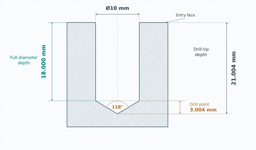
Actual drill-point shapes can differ from a simple cone. Use the selected tool’s geometry when planning production. A shorter point does not automatically make a drill suitable for the material or cutting conditions.
For a bore that will be reamed or finish-bored, the finishing tool introduces another access requirement. Our reaming versus boring guide explains why the tool tip reaching a depth does not prove that the finished diameter reaches it.
Check the Remaining Wall at the Deepest Point
The drill cone consumes material below the usable bore. That matters when the opposite face is close.
Continue the Ø10 mm, 118° example with these hypothetical design requirements:
- Minimum full-diameter depth: 18.000 mm
- Finished part thickness along the hole axis: 24.00 ±0.10 mm
- Required minimum material beneath the deepest point: 2.50 mm
Assume the entry and opposite faces are parallel and perpendicular to the hole axis. The 2.50 mm requirement is an example design input, not a general minimum wall recommendation.
At minimum part thickness, the deepest permitted point is:
23.90 − 2.50 = 21.40 mm
The ideal drill geometry needs a tip depth of approximately:
18.000 + 3.004 = 21.004 mm
The resulting geometric window is approximately:
21.400 − 21.004 = 0.396 mm
That window must accommodate the relevant tool geometry, dimensional variation, depth control, and acceptance requirements. It is not automatically an available machining tolerance.
If the required full-diameter depth increases to 18.500 mm, the same ideal drill point reaches approximately 21.504 mm. At minimum part thickness, only 2.396 mm remains beneath the point, below the specified 2.50 mm requirement.
Increasing usable depth can make the bottom-wall requirement impossible for the proposed geometry, even though the nominal part still looks thick enough.
Possible changes include reducing the required engagement, increasing local thickness, or reviewing a different bottom geometry and machining route. The appropriate choice depends on the feature’s function.
For an angled hole, nearby pocket, curved exterior, or intersecting passage, an axial thickness calculation may miss the closest material boundary. Check the complete geometry and its tolerances.
Full Threads Need Their Own Depth
A blind threaded hole needs complete threads where the fastener must engage. The cutting tap also needs room for its lead and end geometry.
A bottoming tap has a shorter lead than many other tap designs, but it does not form complete threads at its extreme tip. The word “bottoming” does not eliminate bottom clearance.
Keep these requirements separate:
- The required full thread depth and its reference.
- The prepared hole’s usable diameter and depth.
- Space for the chosen tool’s lead, end geometry, and movement.
- Clearance needed to manage chips and avoid bottom contact.
Do not replace that review with one fixed extra-depth allowance for every blind thread. Tap design, pitch, material, chip formation, and available space all affect the requirement. Form tapping avoids cutting chips but still needs suitable material, a controlled prepared hole, and tool clearance.
Cutting chips must also have an evacuation route. In many blind-hole cutting applications, a suitable spiral-flute tap draws chips toward the entrance. Tool selection should follow the actual material and hole conditions.
Where space is restricted, compare the available tapping and thread-milling options. The thread milling versus tapping guide covers that process decision in more detail.
Finally, check the fastener in the assembled position. Its projection below the mating part depends on fastener length and the clamped stack. The tip or incomplete threads can interfere before the joint seats.
A screw that becomes tight before the mating faces close has not demonstrated proper clamping.
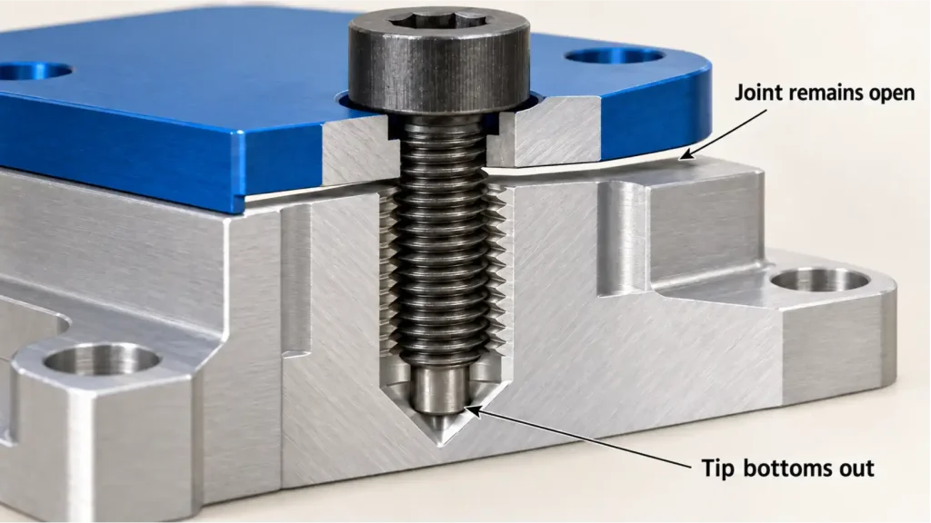
A deeper drill cone may provide tip clearance while adding no complete thread engagement. Conversely, a longer threaded region does not guarantee that an overlong screw can seat without bottoming.
Match the Measurement Contact to the Specified Depth
Before choosing a depth gauge, identify the surface or boundary being accepted.
A narrow probe and a broad, flat-ended rod can stop at different positions in the same conical-bottom hole. A broad rod may contact the cone before reaching its deepest point. That reading does not directly establish either the cone tip or the end of the full-diameter wall.
| Drawing requirement | What the inspection must establish | What an unexplained depth reading can miss |
|---|---|---|
| Minimum full-diameter depth | Where the required cylindrical diameter ends, relative to the reference face | A narrow probe may enter the cone and report a deeper value |
| Maximum depth to the deepest point | The deepest permitted material removal | A broad contact may stop higher on the cone |
| Flat seating depth | The position and required condition of the actual seat | A burr, center feature, or corner contact may stop the probe early |
| Minimum full thread depth | The usable extent of complete threads using an agreed gauging method | Gauge lead geometry and bottom contact can affect apparent insertion |
| Minimum remaining wall | The relationship between the internal bottom and the relevant external surface | A depth measured from one face alone may omit part-thickness variation |
For full-diameter depth, an appropriately designed depth plug may be useful, but its diameter, end shape, lead, and reference must match the intended check. A convenient pin that fits into the hole is not automatically a valid depth gauge.
Likewise, a normal GO/NO-GO thread check should not be assumed to report usable thread depth without a defined depth-verification method. Establish how the gauge’s reference and lead relate to the drawing requirement.
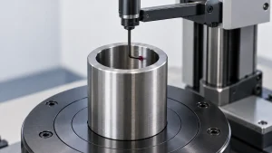
A CMM may evaluate accessible bore and bottom geometry, provided the stylus can reach the necessary surfaces. Distinguish directly measured features from dimensions inferred through a fitted cone or other geometric model. The CMM inspection guide explains why probe access and evaluation strategy belong in the inspection plan.
Clean the hole before measurement. Chips or burrs can create false contact and can also interfere with later assembly. Where retained fluid or debris would affect function, include cleaning and verification requirements in the manufacturing review.
For quotation, provide a section view showing the required usable depth, permitted bottom shape, and nearest material boundary. Include the mating pin or fastener projection when assembly clearance is critical. Through our CNC machining services, RapidEfficient can review whether those requirements leave a practical machining and inspection route before quotation.