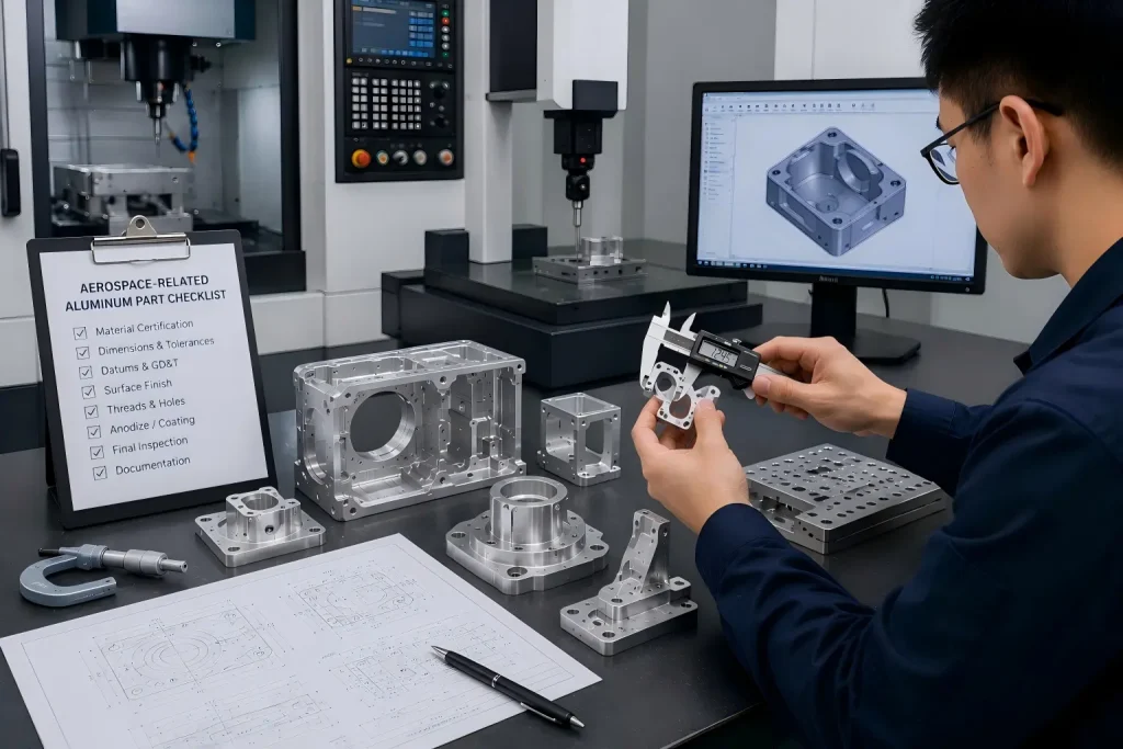
Aerospace aluminum parts are not difficult simply because aluminum needs to be cut accurately.
The larger risks often begin before machining:
- The drawing specifies an alloy but not its temper.
- The material form is unclear.
- Thin walls move after heavy roughing.
- Critical holes are divided between different setups.
- Anodizing changes a bore, thread, or mating surface.
- Inspection requirements do not match the drawing datums.
- Material certification and traceability are discussed only after production begins.
A successful aerospace-related aluminum project therefore depends on more than choosing a CNC machine. Material condition, machining sequence, fixturing, surface treatment, inspection, and documentation must be planned together.
Quick Answer
“Aerospace-grade aluminum” is not one universal material.
It may refer to different aluminum alloys, tempers, product forms, material specifications, and certification requirements. Common examples include 2024, 6061, 7050, and 7075, but each material behaves differently during machining and finishing.
For an accurate CNC quotation, the RFQ should define:
- Aluminum alloy
- Temper
- Plate, bar, extrusion, or forging
- Applicable material specification
- Critical dimensions and datums
- Final surface treatment
- Inspection requirements
- Material certification and traceability
- Any aerospace supplier or special-process approval requirements
The main machining risks usually include residual-stress distortion, thin-wall movement, deep-pocket vibration, datum transfer, burr control, coating allowance, and inspection of the finished part.
What Does “Aerospace-Grade Aluminum” Actually Mean?
The phrase “aerospace-grade aluminum” is widely used, but it is not a complete purchasing specification.
A drawing that says only “aerospace aluminum” leaves several important questions unanswered:
- Which alloy is required?
- What temper is required?
- Is the stock plate, bar, sheet, extrusion, or forging?
- Is a specific material standard required?
- Must the material be traceable by heat, lot, or batch?
- Is grain direction important?
- Is a mill test report required?
- Does the customer require an approved material source?
Aerospace aluminum producers supply multiple alloys as plates, sheets, and extrusions because part performance and manufacturing behavior depend on the complete material condition—not simply the word “aluminum.”
The material callout should therefore be reviewed before quotation and before stock is purchased.
For example:
Aluminum 7075-T651 plate
is more useful than:
Aerospace aluminum
But even the first callout may still require an applicable material standard, stock thickness, certification level, and traceability requirement.
Common Aluminum Alloys for Aerospace-Related CNC Parts
There is no single “best” aerospace aluminum alloy. The correct choice depends on loading, environment, corrosion requirements, stock thickness, finishing, cost, and the customer’s approved material specification.
2024 Aluminum
2024 is commonly associated with high-strength aerospace applications and is available in several tempers and product forms.
From a machining-planning perspective, important questions include:
- Which temper is required?
- Does the project require clad or bare material?
- What corrosion-protection process will follow machining?
- Are fatigue-sensitive surfaces or edge conditions identified?
- Is the material being purchased as sheet, plate, or another form?
A drawing should not simply replace a complete 2024 specification with the phrase “aircraft aluminum.”
6061 Aluminum
6061 is widely available and practical for many custom machined parts.
It may be considered for:
- Test fixtures
- Mounting brackets
- Equipment housings
- Adapter plates
- Prototype structures
- Ground-support equipment
- Non-flight-critical aerospace-related components
Its availability and general manufacturing flexibility can make it suitable for development and equipment projects. However, it should not be selected only because it is easier to source. Required strength, fatigue performance, environment, joining method, and customer specification still control material selection.
For a broader comparison, see our guide to 6061 vs 7075 aluminum for CNC machining.
7050 Aluminum
7050 is supplied in high-strength aerospace plate conditions and is often considered where toughness, stress-corrosion performance, and thick-section behavior matter.
Its use should be based on the actual drawing and approved material specification. Availability, minimum purchase quantity, stock thickness, temper, certification, and machining allowance can affect both cost and lead time.
7075 Aluminum
7075 is one of the best-known high-strength aluminum alloys used in aerospace-related engineering.
However, “7075” alone is not enough information.
Different tempers can change:
- Mechanical properties
- Stress-corrosion behavior
- Residual-stress condition
- Stock availability
- Machining stability
- Surface-treatment planning
For example, T651 and T7351 should not be treated as interchangeable labels. Aerospace plate suppliers list multiple alloy-and-temper combinations because material condition is part of the engineering requirement.
Why Temper and Stock Form Matter
The alloy number describes only part of the material.
Temper designations such as T3, T351, T6, T651, T7351, and T7451 describe different processing and material conditions. The suffix may also indicate a stress-relief route or other treatment that affects how the stock behaves during machining.
Stock form matters as well.
The same alloy may be purchased as:
- Rolled plate
- Sheet
- Extruded bar
- Extruded profile
- Forging
- Drawn or cold-finished product
These forms are not automatically equivalent.
They may differ in:
- Grain direction
- Residual stress
- Property direction
- Available thickness
- Flatness
- Surface condition
- Dimensional movement after material removal
- Certification and approved specifications
Reduced-residual-stress aerospace plate is specifically marketed for improved machining stability and reduced movement in complex machined parts, which shows why stock condition must be considered before cutting begins.
For large pockets, thin ribs, or parts machined from thick plate, the purchasing specification can influence the final dimensional result as much as the finishing toolpath.
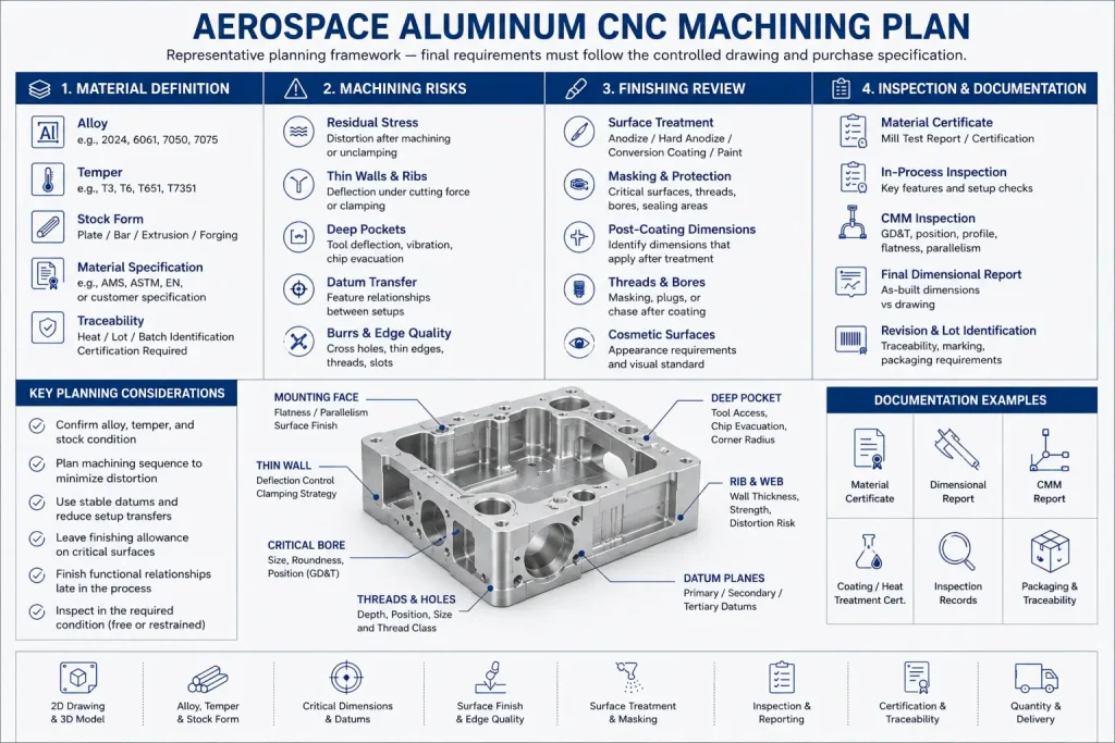
Main Challenges in Aerospace Aluminum CNC Machining
1. Residual-Stress Distortion
A plate may appear flat and stable before machining.
Once a large amount of material is removed, the balance of internal stress can change. The part may move:
- During roughing
- After unclamping
- Between setups
- During finishing
- After surface treatment
- During final inspection
Common symptoms include:
- Bowed base surfaces
- Twisted frames
- Thin walls leaning inward or outward
- Flatness changing after unclamping
- Hole positions shifting relative to finished datums
- A part passing in the fixture but failing in the free state
Distortion cannot always be eliminated, but it can be planned for.
Possible controls include:
- Selecting a suitable stock condition
- Removing material in balanced stages
- Avoiding excessive local heat
- Leaving finishing allowance
- Releasing and re-establishing the part between stages
- Finishing critical features after major roughing
- Inspecting the part in the required free or restrained condition
The correct strategy depends on geometry. There is no universal roughing sequence for all aerospace aluminum parts.
2. Thin Walls, Ribs, and Floors
Lightweight parts often contain:
- Thin walls
- Deep pockets
- Narrow ribs
- Large unsupported floors
- High material-removal ratios
- Small corner radii
- Long-reach features
These features can deflect under cutting force or clamping pressure.
A dimension measured while the tool is cutting may not match the same dimension after the wall springs back. Excessive clamping can create a similar problem: the part looks correct in the fixture but moves when released.
Machining planning may require:
- Supporting weak areas without over-constraining them
- Roughing opposite areas in stages
- Using lighter finishing passes
- Reducing unnecessary tool reach
- Controlling chip evacuation
- Avoiding heat concentration
- Leaving fragile walls until later operations
- Verifying dimensions after unclamping
For more general aluminum design and machining guidance, see our aluminum machining guide.
3. Deep Pockets and Long Tool Reach
A deep pocket does not only increase machining time.
It may also create:
- Tool deflection
- Chatter
- Poor chip evacuation
- Built-up material on cutting edges
- Inconsistent wall finish
- Corner-radius limitations
- Difficulty reaching the bottom with a rigid tool
- Increased risk of damaging thin ribs
A very small internal corner radius can force the use of a smaller and longer cutter than the rest of the geometry requires.
Where function permits, increasing the corner radius may allow:
- A stronger cutting tool
- Shorter machining time
- Better wall finish
- More stable dimensions
- Lower tool-breakage risk
Internal radii should therefore be selected from both assembly requirements and tool-access conditions.
4. Datum Transfer Between Setups
Aerospace-related parts often contain features on several sides.
The problem is not simply machining each feature. The features must remain correctly related to one another.
Typical relationships include:
- Bore axis to mounting face
- Hole pattern to external profile
- Mating surface to alignment slot
- Counterbore to datum plane
- Parallel mounting faces
- Sensor bore to connector interface
Every setup introduces another opportunity for datum-transfer error.
The process plan should identify:
- Primary, secondary, and tertiary datums
- Which critical features can be machined in one setup
- Which surfaces are reliable for later location
- Whether temporary machining datums are required
- How the inspection setup will reproduce the drawing reference system
Our CNC machining tolerances guide explains why feature function and datum relationships matter more than applying the tightest tolerance to every dimension.
5. Burrs and Edge Conditions
Aluminum can form burrs around:
- Cross holes
- Intersecting passages
- Thin edges
- Slots
- Threads
- Counterbores
- Deep pockets
- Exit surfaces
A drawing that states only “deburr all edges” may not fully define the requirement.
The customer may need to specify:
- Maximum permitted edge break
- Sharp edges that must remain functional
- Sealing edges
- Electrical-contact areas
- Flow-path cleanliness
- Thread-start condition
- Prohibited loose particles
- Inspection method
An aggressive manual edge break can damage a sealing surface or alter a small feature. Burr removal must therefore be matched to the function of the edge.
A Practical Roughing and Finishing Strategy
Aerospace aluminum CNC machining should begin with a process review rather than a default toolpath.
A typical planning sequence may include:
1. Confirm the Material
Review:
- Alloy
- Temper
- Stock form
- Material specification
- Certification
- Grain-direction requirements
- Available stock thickness
2. Establish Stable Datums
Choose surfaces that can support both machining and inspection.
Temporary stock or sacrificial features may be useful when the finished part does not provide enough stable clamping area.
3. Remove Bulk Material in Stages
Heavy material removal may be divided across the component instead of completing one deep area while the opposite side remains solid.
This can help reduce unbalanced movement, but the best sequence remains geometry-dependent.
4. Leave Controlled Finishing Allowance
Critical walls, floors, holes, and mating faces should retain enough material for stable finishing.
Too little allowance may not remove roughing variation. Too much allowance can create another heavy cutting operation during the finishing stage.
5. Release and Recheck the Part
For distortion-sensitive geometry, the part may need to be unclamped, allowed to relax, and re-established before final machining.
6. Finish Functional Relationships Late
Critical bores, datum surfaces, sealing faces, and related hole patterns are often most reliable when machined after major material removal has been completed.
7. Inspect in the Required Condition
The drawing or inspection plan should define whether the part is measured:
- Free state
- Restrained
- As machined
- After coating
- After assembly
- At a controlled temperature
A fixture should not be allowed to hide a dimensional problem that appears after the part is released.
When Five-Axis Machining Helps
Five-axis machining may be useful for parts with:
- Features on several faces
- Angled bores
- Complex access directions
- Deep contoured surfaces
- Difficult datum relationships
- Short tool-clearance requirements
Its main benefit may be the ability to reach more features with fewer repositioning operations.
That can reduce some setup transfers and may improve access with shorter tools.
However, five-axis machining does not automatically guarantee:
- Tighter tolerances
- Better surface finish
- Shorter lead time
- Lower cost
- Zero distortion
The result still depends on:
- Part rigidity
- Fixture design
- Tool length
- Machine condition
- Toolpath
- Datum strategy
- Thermal control
- Inspection method
Simple prismatic parts may be produced more efficiently with three-axis machining and well-planned fixtures. Process selection should follow the geometry, not a marketing preference for the machine with more axes.
Surface Treatment Must Be Included in the Dimensional Plan
Aerospace-related aluminum parts may require:
- Anodizing
- Hard anodizing
- Chemical conversion coating
- Painting
- Primer
- Project-specific protective coating
The finishing specification should be confirmed before final dimensions are planned.
Important questions include:
- Which surfaces receive treatment?
- Which surfaces must be masked?
- Are bores treated or protected?
- Are threads masked, plugged, or chased afterward?
- Which dimensions apply before treatment?
- Which dimensions apply after treatment?
- Are electrical-contact areas required?
- Are sealing faces allowed to receive coating?
- Is color cosmetic, functional, or both?
- Is a coating certificate required?
Coating behavior is not represented accurately by applying one universal dimensional allowance to every surface.
The effect depends on the treatment type, specification, process control, geometry, masking, and measurement method. Critical fits should be reviewed individually.
For available CNC aluminum processing and finishing coordination, see our CNC aluminum machining services.
Inspection Planning for Aerospace Aluminum Parts
Inspection should be planned from the drawing datums and functional requirements.
Depending on the project, verification may include:
- Incoming material and certificate review
- First-piece dimensional inspection
- In-process inspection
- Final dimensional report
- CMM inspection
- Height-gauge and surface-plate inspection
- Bore measurement
- Thread verification
- Surface-roughness measurement
- Flatness and parallelism checks
- Visual and burr inspection
- Coating documentation
- Final identification and packaging review
The inspection method must suit the feature.
For example:
- A caliper may be adequate for a noncritical overall size.
- A bore gauge may be more appropriate for a functional bore.
- A CMM may be needed for positional or profile relationships.
- A surface plate may be necessary for flatness evaluation.
- A roughness instrument may be required when Ra is specified.
Our quality assurance process explains how inspection scope can be coordinated according to drawing and project requirements.
Documentation and Aerospace Approval Boundaries
Not every aerospace-related part requires the same paperwork.
A prototype fixture, ground-test housing, development bracket, and production flight component can have very different approval requirements.
The RFQ should identify whether the customer requires:
- Material certificate
- Mill test report
- Lot traceability
- Certificate of conformity
- Dimensional inspection report
- CMM report
- First-article inspection
- Coating or heat-treatment certificate
- Serialized identification
- Revision control
- Approved material source
- Customer-approved special-process supplier
- Record-retention requirements
AS9100 includes additional aviation, space, and defense quality-management requirements beyond ISO 9001. Nadcap is an industry-managed accreditation system for aerospace critical processes. These requirements should never be assumed from a general CNC machining quotation.
When AS9100 certification, Nadcap-controlled processing, OEM approval, or another customer-specific qualification is mandatory, it must be stated before quotation and supplier selection.
What Drives Cost and Lead Time?
The alloy price is only one part of the total cost.
Major cost drivers may include:
- Certified material availability
- Minimum stock purchase
- Plate thickness
- High material-removal ratio
- Thin-wall distortion risk
- Number of setups
- Five-axis machine time
- Long-reach tooling
- Small internal radii
- Tight hole-position requirements
- Extensive deburring
- Surface-treatment masking
- Post-coating inspection
- CMM programming
- Full dimensional reports
- First-article documentation
- Traceability and packaging requirements
A design can sometimes be simplified without changing its function.
Possible DFM improvements include:
- Increasing nonfunctional internal radii
- Removing unnecessarily deep pockets
- Standardizing hole sizes
- Separating cosmetic and critical surfaces
- Defining only genuinely functional tight tolerances
- Providing clear datum references
- Identifying post-coating dimensions
- Allowing suitable stock thickness
These decisions are most effective before the quotation is finalized.
RFQ Checklist for Aerospace Aluminum CNC Machining
For a useful technical review, provide:
- 3D CAD model
- Controlled 2D drawing
- Drawing revision
- Aluminum alloy
- Temper
- Stock form
- Applicable material specification
- Quantity
- Prototype or production stage
- Critical dimensions
- Datum scheme
- Geometric tolerances
- Surface-roughness requirements
- Edge and burr requirements
- Surface treatment
- Masking requirements
- Dimensions that apply after treatment
- Inspection report requirements
- Material certification
- Traceability requirements
- Required supplier or special-process approvals
- Packaging and identification instructions
Missing information should be clarified before material is purchased or machining begins.
How Rapid Efficient Supports Aerospace-Related Projects
Rapid Efficient supports custom CNC machining for aerospace-related:
- Development prototypes
- Test fixtures
- Inspection fixtures
- Lightweight housings
- Mounting brackets
- Adapter plates
- Sensor housings
- Equipment components
- Selected low-volume aluminum parts
Support may include:
- Drawing and manufacturability review
- Aluminum-alloy and stock-form discussion
- Machining-process planning
- Prototype and low-volume production
- Surface-finishing coordination
- Dimensional inspection
- CMM reports when requested
- Material documentation when requested
- Packaging and international delivery coordination
Project capability depends on the drawing, alloy, tolerances, documentation scope, surface treatment, quantity, and required aerospace approvals.
For a broader overview, visit our aerospace manufacturing support.
FAQ
What is the best aluminum alloy for aerospace CNC machining?
There is no universal best alloy.
2024, 6061, 7050, and 7075 serve different design and manufacturing requirements. Selection should follow the customer specification, loading, corrosion environment, stock form, temper, finishing, and approval requirements.
Is 7075 always better than 6061?
No.
7075 generally offers higher strength in commonly compared conditions, but 6061 may provide advantages in availability, corrosion behavior, joining, cost, and general manufacturing flexibility.
The better choice is the alloy that meets the complete functional requirement.
Why can an aluminum part move after machining?
Material removal may release residual stress. Thin walls can also deflect under clamping and cutting forces.
Movement may appear during roughing, after unclamping, during surface treatment, or at final inspection.
Does five-axis machining automatically improve accuracy?
No.
Five-axis machining can improve tool access and reduce some repositioning operations, but final accuracy still depends on fixturing, tool length, machine condition, datum planning, part rigidity, process control, and inspection.
Should anodizing be applied before or after final inspection?
This depends on the drawing.
Some dimensions may be inspected before treatment, while critical finished dimensions may require verification after treatment. The drawing should clearly identify which condition controls acceptance.
Can aerospace aluminum parts hold tight tolerances?
Selected features may hold tight tolerances after engineering review.
Feasibility depends on feature size, wall thickness, geometry, material condition, tool access, setup strategy, surface treatment, temperature, and inspection method. Tight tolerances should be applied to functional features rather than every dimension.
What documents can be supplied with machined parts?
Depending on project requirements, documentation may include material certificates, dimensional reports, CMM reports, certificates of conformity, coating documentation, and revision or lot identification.
The required package should be confirmed before quotation.
Request a Technical Review
Send Rapid Efficient your 2D drawing, 3D model, alloy and temper, quantity, surface-treatment requirements, and inspection expectations.
We will review the material specification, thin-wall and distortion risks, datum strategy, tool access, finishing requirements, documentation scope, and quotation details before production planning.