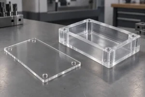
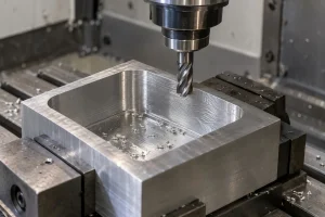
Quick Answer: Common faulty structures in mechanical design include poor load distribution, wrong material selection, improper tolerances and clearances, weak structural support, sharp internal corners, thin-wall deformation, and poor datum planning. These problems can cause stress concentration, vibration, assembly interference, machining deformation, higher cost, and early part failure. To avoid them, engineers should review load paths, material behavior, wall thickness, tolerance stack-up, machining feasibility, and inspection requirements before production.
1. Introduction
Mechanical design affects more than product appearance. A small structural mistake can create stress concentration, deformation, vibration, assembly interference, machining difficulty, or early part failure.
For CNC machined parts, faulty structures often appear when the drawing looks correct on screen but ignores material behavior, machining access, clamping force, wall thickness, tolerance stack-up, and inspection method. These problems may increase machining cost, extend lead time, or cause parts to fail during assembly.
This guide explains common faulty structures in mechanical design and how buyers and engineers can reduce risk before sending parts for CNC machining or small-batch production.
| Fault Type | What Goes Wrong | Possible Impact |
|---|---|---|
| Poor load distribution | Stress is concentrated in weak areas | Cracks, deformation, fatigue, or early failure |
| Incorrect material selection | Material strength, hardness, corrosion resistance, or machinability does not match the application | Higher cost, poor durability, or machining difficulty |
| Improper tolerance and clearance | Fits are too tight, too loose, or not aligned with assembly function | Interference, looseness, friction, noise, or assembly failure |
| Weak structural support | Thin walls, unsupported bosses, or long overhangs deform under load | Vibration, bending, poor stability, or scrap |
| Sharp internal corners | Stress concentrates at corners or tool access becomes difficult | Cracking risk, tool wear, higher machining cost |
| Poor datum planning | Functional surfaces do not match machining or inspection datums | Tolerance stack-up, misalignment, or inspection disputes |
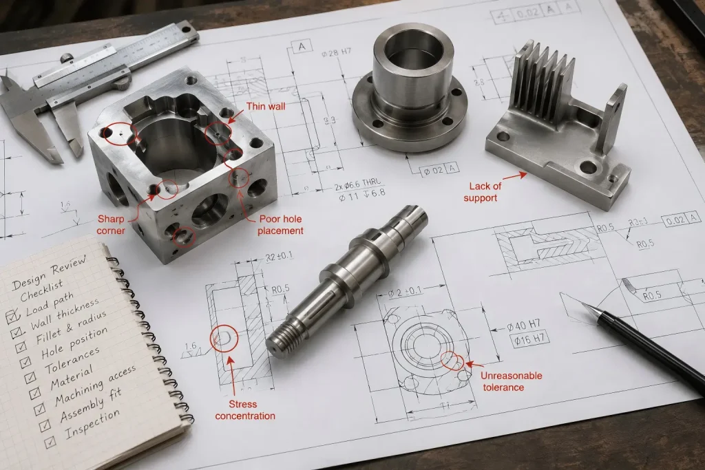
2. Common Faulty Structures in Mechanical Design
2.1 Poor Load Distribution
Poor load distribution happens when force is concentrated on a small area instead of being spread through the structure. This can create stress concentration, bending, fatigue cracks, or premature failure.
In CNC machined parts, this problem often appears in thin brackets, mounting plates, long arms, unsupported ribs, and parts with sudden section changes. Engineers should check load paths, wall thickness, fillets, rib placement, and screw hole locations before production.
2.2 Incorrect Material Selection
A good structure can still fail if the material is not suitable. Material selection should consider strength, stiffness, wear resistance, corrosion resistance, heat resistance, weight, machinability, surface finishing, and cost.
For example, aluminum may be good for lightweight housings, stainless steel may be better for corrosion resistance, brass or copper may be selected for conductivity, and engineering plastics may work for insulation or low-friction applications. The right material should match both function and manufacturing process.
2.3 Improper Tolerance and Clearance
Tolerance and clearance mistakes are common in mechanical assemblies. If tolerances are too tight, the part may be expensive to machine and difficult to assemble. If tolerances are too loose, the assembly may have vibration, noise, poor alignment, or functional instability.
Designers should apply tight tolerances only to functional features such as bearing seats, sealing surfaces, alignment holes, sliding fits, threaded interfaces, and datum-related features.
For tolerance planning, buyers can compare standard, precision, and tight requirements using a CNC machining tolerance chart before sending RFQ files.
2.4 Poor Structural Stability
Poor structural stability can cause bending, buckling, vibration, or deformation during machining or actual use. This often happens when walls are too thin, ribs are missing, support points are weak, or the structure has long unsupported features.
For CNC machining, structural stability should also consider clamping. A part may look strong in CAD but deform when held in a fixture or after material is removed.
2.5 Sharp Internal Corners and Stress Concentration
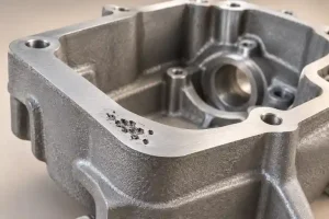
Sharp internal corners can create stress concentration and make CNC machining more difficult. Milling tools have a physical radius, so very sharp internal corners may require smaller tools, slower machining, EDM, or design changes.
Adding suitable fillets or relief features can reduce stress concentration, improve tool access, and lower machining cost.
2.6 Poor Datum and Assembly Reference Planning
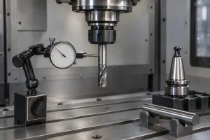
A part can have correct dimensions but still fail if the datum strategy is wrong. If the design datum, machining datum, and inspection datum do not match the functional assembly requirement, holes, faces, and mating surfaces may not align correctly.
For related setup and inspection concepts, see our guide to types of CNC machining datums.
3. How Faulty Structures Affect CNC Machining
Faulty mechanical structures do not only affect product performance. They also make CNC machining more difficult, more expensive, and less stable.
| Design Problem | CNC Machining Risk | Practical Fix |
|---|---|---|
| Thin walls without support | Clamping deformation, vibration, poor flatness | Add ribs, increase wall thickness, or plan soft support |
| Deep narrow pockets | Tool deflection, chatter, poor surface finish | Increase corner radius, reduce pocket depth, or allow larger tools |
| Sharp internal corners | Small tools, long machining time, higher tool wear | Add fillets or relief features |
| Overly tight tolerances | Higher cost, more inspection, higher scrap risk | Tighten only functional features |
| Poor datum selection | Misalignment, inspection disputes, tolerance stack-up | Define functional datums clearly |
| Unbalanced material removal | Warping, bending, unstable dimensions | Use balanced machining and rough-rest-finish strategy |
Poor structure and tight tolerance often create hidden CNC machining tolerance stack-up across holes, faces, and assembly features.
4. How to Prevent Faulty Structures Before CNC Machining
Preventing faulty structures should happen before production starts. Once a poor structure enters machining, the supplier may only be able to reduce risk, not fully fix the design.
4.1 Review Load Paths and Stress Areas
Check where forces enter the part, where they transfer, and where stress may concentrate. Long unsupported arms, thin sections, sharp corners, and sudden thickness changes should be reviewed carefully.
4.2 Match Material to Function
Material should be selected based on strength, stiffness, corrosion resistance, wear resistance, weight, conductivity, heat resistance, and machining difficulty. Over-specifying material can increase cost, while under-specifying material can cause failure.
4.3 Use Practical Tolerances and Clearances
Avoid applying tight tolerances to every feature. For CNC machined parts, tight tolerances should be reserved for surfaces that affect assembly, sealing, motion, alignment, or function.
4.4 Improve Machining Access
Designers should consider tool access, corner radius, hole depth, thread depth, pocket shape, and clamping direction. Better machining access usually reduces cost, tool wear, and lead time.
4.5 Review Design Before RFQ
Before sending drawings for quotation, review the part for wall thickness, datum selection, tolerance stack-up, material choice, surface finish, and inspection requirements.
For broader manufacturability review, buyers can also refer to our CNC machining design guide before finalizing mechanical part drawings.
FAQ: Faulty Structures in Mechanical Design
What are common faulty structures in mechanical design?
Common faulty structures include poor load distribution, wrong material selection, improper tolerance and clearance, weak structural support, sharp internal corners, thin-wall deformation, and poor datum planning.
Why do faulty structures cause CNC machining problems?
Faulty structures can cause clamping deformation, tool deflection, chatter, poor surface finish, tolerance stack-up, higher machining cost, and inspection problems.
How can designers reduce structural faults?
Designers can reduce structural faults by reviewing load paths, wall thickness, fillets, ribs, datum selection, material behavior, tolerance requirements, and machining access before production.
Why are sharp internal corners a problem?
Sharp internal corners can create stress concentration and may require very small cutting tools, slower machining, EDM, or design changes. Adding proper fillets can improve both strength and machinability.
Are tight tolerances always better?
No. Unnecessary tight tolerances increase machining cost, inspection time, lead time, and scrap risk. Tight tolerances should only be applied to features that affect assembly, sealing, alignment, or function.
What should buyers provide before quoting mechanical parts?
Buyers should provide 2D drawings, 3D CAD files, material grade, tolerance requirements, datum information, surface finish, inspection needs, quantity, and application notes.
Conclusion
Common faulty structures in mechanical design can cause machining difficulty, higher cost, unstable quality, assembly problems, and early part failure. Many of these issues start from poor load distribution, incorrect material selection, impractical tolerances, weak structural support, sharp internal corners, or poor datum planning.
For CNC machined parts, design and manufacturing should be reviewed together. A part that looks correct in CAD may still be difficult to clamp, machine, inspect, or assemble if structural details are not practical.
Rapid Efficient can review drawings, material requirements, tolerance risks, datum strategy, surface finish needs, and inspection requirements before quotation to help identify possible mechanical design and CNC machining risks.