In CNC machining, positioning is not only about holding a part in place. It controls how the workpiece is located, clamped, machined, inspected, and repeated across multiple setups. A weak positioning method can create datum error, tolerance stack-up, poor hole alignment, surface mismatch, and assembly problems.
For tight-tolerance CNC parts, the right positioning method depends on the 3-2-1 rule, datum selection, fixture stability, clamping force, probing method, material behavior, and inspection requirements. A single setup may look accurate, but poor repeatability between setups can still turn small errors into expensive scrap.
For related setup reference concepts, see our guide to types of CNC machining datums and how datum choice affects machining, probing, and inspection.
1.What is Machining Positioning Method?
Machining positioning method refers to the techniques and approaches used to precisely determine the position of a workpiece or a cutting tool during the machining process. It’s like giving clear directions to both the part being worked on and the tool that’s doing the work, ensuring everything is in the right place for accurate and efficient machining operations.
In simple terms, imagine you’re building a model and you need to put the pieces together exactly where they should be. Machining positioning method does the same thing in the manufacturing world. For example, in milling operations, it helps to set the position of the workpiece on the table so that the milling cutter can remove the right amount of material from the exact locations needed to create the desired shape.
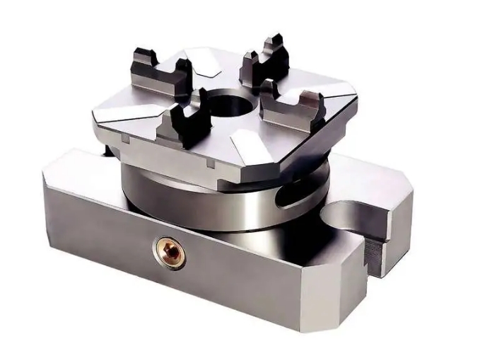
There are various types of positioning methods. One common way is using mechanical stops or fixtures. These are like fixed points that the workpiece can rest against or be clamped to, guaranteeing it stays in a specific position. Another approach could involve using sensors and measurement systems. They can detect the position of the workpiece or tool and send signals to adjust if there’s any deviation from the intended position.
Accurate machining positioning is crucial as it directly impacts the quality of the final product. If the positioning is off even by a small margin, it can lead to parts that don’t fit together properly, have incorrect dimensions, or don’t meet the required tolerances. And in today’s highly competitive manufacturing market where products need to be of high quality and consistent, having reliable machining positioning methods is more important than ever.
Moreover, with the development of advanced manufacturing technologies like CNC (Computer Numerical Control) machining, the role of precise positioning methods has become even more significant. CNC machines rely on accurate positioning instructions programmed into them to carry out complex machining tasks with high repeatability and precision.For custom CNC machined parts, positioning should be reviewed together with the drawing datum, machining datum, fixture design, clamping method, and inspection plan. A good positioning strategy can reduce setup error, improve repeatability, and make critical dimensions easier to verify. It allows manufacturers to produce more parts in less time while maintaining excellent quality standards, which is a huge advantage in attracting customers and staying ahead in the market.
2. The Basics of Machining Positioning
Different Types of Positioning Techniques
In the world of machining, several positioning techniques are commonly used, each with its own unique characteristics. Let’s take a look at some of them.
One of the basic positioning techniques is mechanical positioning. This involves using fixtures, jigs, and stops. For example, a simple vise on a milling machine table can act as a fixture to hold a workpiece firmly in place. The workpiece is clamped against the fixed jaws of the vise, ensuring it doesn’t move during the machining process. Jigs, on the other hand, are often designed with specific holes or slots that help guide the cutting tool to the exact positions needed on the workpiece. Stops can be set to limit the movement of the workpiece along certain axes, providing a precise reference point for machining. This type of positioning is reliable and relatively straightforward, but it may require some time to set up properly depending on the complexity of the workpiece.
Another technique is optical positioning. With the help of lasers or optical sensors, the position of the workpiece or the cutting tool can be detected with high precision. Lasers can project a beam onto the workpiece surface, and by measuring the reflection or interference patterns, the exact location can be determined. Optical sensors can also detect edges or specific markings on the workpiece. This technique is particularly useful when dealing with very fine or delicate machining tasks where accuracy in the micrometer range is required. For instance, in the production of precision optical components like lenses, optical positioning ensures that the curvature and thickness are machined to exact specifications.
Then there’s electrical positioning. This often involves using encoders or other electrical sensing devices. Encoders are attached to the moving parts of the machine, such as the spindle or the linear axes. They convert the mechanical movement into electrical signals that can be read by the machine’s control system. The control system then uses this information to adjust the position of the cutting tool or workpiece as needed. This allows for real-time monitoring and correction of any positioning errors, making it ideal for high-speed machining operations where quick adjustments are essential.
Lastly, we have magnetic positioning. In some specialized machining setups, magnetic fields are used to hold and position the workpiece. Magnetic chucks hold suitable ferromagnetic workpieces against the chuck surface or supporting pole extensions. This is especially handy when working with materials that are difficult to clamp using traditional mechanical methods or when minimizing any potential damage to the workpiece surface is crucial. For example, in the machining of thin and brittle magnetic materials, magnetic positioning can offer a gentle yet precise way to hold the workpiece during the cutting process.
Each of these positioning techniques has its advantages and is chosen based on factors like the type of workpiece, the required machining accuracy, and the overall production efficiency goals.
| Positioning Method | Typical Use | Main Advantage | Buyer Should Check |
|---|---|---|---|
| Mechanical stops and fixtures | General CNC milling and turning setups | Simple, durable, cost-effective | Datum repeatability, clamping force, fixture wear |
| 3-2-1 positioning | Prismatic parts, plates, brackets, housings | Controls six degrees of freedom clearly | Primary, secondary, and tertiary datum selection |
| Probing / work offset positioning | CNC setups requiring repeatable zero points | Reduces manual setup variation | Probe access, calibration, datum surface quality |
| Soft jaws / custom fixtures | Round parts, thin-wall parts, repeat production | Improves part support and repeatability | Deformation risk, jaw wear, setup consistency |
| Vacuum or magnetic holding | Thin plates or parts difficult to clamp mechanically | Reduces visible clamp marks | Holding force, material compatibility, cutting load |
| Optical / sensor-assisted positioning | Special inspection or alignment tasks | Non-contact reference support | Whether it is practical for the actual machining setup |
Importance of Accurate Positioning in Machining
Accurate positioning in machining is of utmost importance and directly impacts the final quality and precision of the products being manufactured.
When it comes to dimensional accuracy, precise positioning ensures that every cut, hole, or surface finish is exactly where it should be. For example, in the automotive industry, engine components need to be machined with extremely tight tolerances. If the positioning of the crankshaft or cylinder bore machining is off even by a fraction of a millimeter, it can lead to poor engine performance, increased fuel consumption, and even premature wear and failure of the engine. In the production of aircraft parts as well, accurate positioning is critical. Wings, fuselage sections, and other structural components must fit together precisely to maintain the integrity and safety of the aircraft during flight. A misaligned hole for a rivet or a slightly off-positioned surface can compromise the structural strength of the entire plane.
Surface finish quality also depends on accurate positioning. When a cutting tool is positioned correctly relative to the workpiece, it can create smooth and consistent surfaces. In contrast, incorrect positioning might result in tool chatter, which leaves visible marks and an uneven finish on the workpiece. This is particularly significant in industries like medical device manufacturing, where implants or surgical instruments need to have a high-quality surface finish to ensure biocompatibility and proper functioning inside the human body.
Moreover, accurate positioning plays a key role in repeatability. In mass production environments, manufacturers need to produce thousands or even millions of identical parts. With precise positioning methods, each part can be machined with the same level of accuracy as the previous one. This is where rapidefficient comes into the picture in the CNC machining market. A stable positioning strategy can reduce setup variation between different machining operations. For custom CNC machined parts, positioning should be reviewed together with the drawing datum, machining datum, fixture design, clamping method, and inspection plan. For instance, it can quickly and accurately position the workpiece for the next cutting pass or tool change, allowing the CNC machine to operate continuously with minimal downtime. This not only improves the overall productivity but also ensures that the quality of the parts remains consistent throughout the production run. It enables manufacturers to meet tight delivery schedules while maintaining excellent quality standards, which is a major factor in attracting customers and staying competitive in today’s global manufacturing landscape.
In conclusion, accurate positioning in machining is the foundation for producing stable, repeatable, and reliable CNC parts. For custom CNC machined parts, positioning should be reviewed together with datum selection, fixture design, clamping force, machining sequence, and inspection planning.
Poor positioning does not only affect one dimension. Across multiple setups, it can create hidden CNC machining tolerance stack-up between holes, faces, bores, and assembly features.
💡 Shop Floor Insight: The Hidden Error
Many positioning problems do not come from the fixture design alone. They come from repeatability. Even with a correct 3-2-1 setup, inconsistent clamping force, burrs on datum surfaces, fixture wear, or uneven part contact can make tight-tolerance features drift between operations.
For thin-wall parts or parts with critical hole alignment, repeatable clamping and clean datum surfaces are often more important than simply increasing clamping force.
3. How Positioning Method Affects CNC Machining Accuracy
A positioning method affects more than setup speed. It controls how the workpiece repeats from operation to operation and whether critical features remain aligned to the drawing datum.
Poor positioning can create several problems:
| Positioning Problem | Possible Machining Result |
|---|---|
| Weak primary datum | Flatness, parallelism, or height error |
| Unstable clamping | Part movement, chatter, or inconsistent dimensions |
| Wrong machining datum | Holes and faces do not match the functional assembly datum |
| Too many setups | Accumulated alignment error between features |
| Poor repeatability | First part is acceptable, but later parts drift |
| Inspection datum mismatch | CMM result does not match the drawing intent |
For precision CNC machining, positioning should be planned before cutting starts. The supplier should check the drawing datum, fixture contact points, clamping sequence, tool access, probing method, and inspection datum together.
If the drawing includes tight dimensional requirements, compare them with a practical CNC machining tolerance chart before deciding which features truly need tighter setup control.
4. Machining Positioning in Practice
In real CNC machining projects, positioning choices are usually made based on part shape, material, tolerance, quantity, and inspection requirements. The goal is not to use the most advanced method everywhere, but to use a method that is stable, repeatable, and suitable for the part.
Practical Examples
| Part Type | Common Positioning Challenge | Practical Positioning Approach |
|---|---|---|
| Thin-wall aluminum housing | Clamping can deform the wall or change flatness | Use balanced support, reduced clamping force, and rough-rest-finish strategy |
| Motor housing | Bore, face, and bolt pattern must stay aligned | Use functional datums, custom fixture, probing, and CMM verification |
| Bracket with multiple holes | Hole position can drift between setups | Use 3-2-1 positioning, common datum surfaces, and controlled re-clamping |
| Turned shaft part | Concentricity depends on chucking and support | Use soft jaws, centers, steady rest, or controlled turning sequence |
| Plate part | Large flat surface may not be perfectly stable | Use selected datum pads, vacuum fixture, or balanced mechanical support |
| Precision fixture component | Multiple faces and holes must match assembly intent | Align machining datum with inspection datum and verify critical features |
These examples are more useful than generic success stories because they show how positioning decisions affect real machining risk.
5. Working With Rapid Efficient on CNC Positioning and Setup Review
For custom CNC machined parts, positioning method should be reviewed together with the drawing datum, machining datum, fixture plan, clamping method, probing strategy, and inspection requirement.
Rapid Efficient can review 2D drawings, 3D files, tolerance requirements, material condition, surface finish needs, and critical assembly features before quotation. For broader drawing preparation, tolerance planning, and manufacturability review, buyers can also refer to our CNC machining design guide before sending RFQ files.This helps identify possible setup risks, datum mismatch, clamping deformation, and inspection issues before production starts.
For aluminum, stainless steel, copper, brass, titanium, and engineering plastic parts, the positioning method may affect hole alignment, bore concentricity, flatness, perpendicularity, surface matching, and final assembly fit.
Rapid Efficient is suitable for buyers who need custom CNC machined parts, fast RFQ communication, practical drawing review, finishing coordination, inspection discussion, and export support.
Why Buyers Work With Rapid Efficient
- Drawing review before quotation
- CNC machining support for custom metal and plastic parts
- Fixture and setup risk discussion for tight-feature components
- Surface finishing and inspection coordination
- Prototype and low-volume production support
- Export packaging and communication support
The right positioning method depends on part geometry, material, tolerance, quantity, and inspection requirements. For critical CNC parts, setup planning should be confirmed before production rather than corrected after machining.
FAQ: Machining Positioning
What is machining positioning?
Machining positioning is the way a workpiece is located and supported before cutting. It defines how the part sits in the fixture, how the CNC machine sets the work coordinate system, and how features are machined relative to the datum.
What is the 3-2-1 rule in CNC machining?
The 3-2-1 rule is a common positioning principle used to control six degrees of freedom. Three points locate the primary datum, two points locate the secondary datum, and one point locates the tertiary datum. This helps make setup more repeatable.
Why does positioning matter for tight-tolerance CNC parts?
Poor positioning can cause datum error, tolerance stack-up, hole misalignment, flatness problems, concentricity error, and inspection mismatch. Even if each feature looks acceptable, several small setup errors can combine into assembly problems.
What positioning methods are commonly used in CNC machining?
Common methods include mechanical stops, 3-2-1 positioning, probing and work offsets, soft jaws, custom fixtures, vacuum fixtures, magnetic holding, and sensor-assisted alignment. The right method depends on part shape, material, tolerance, quantity, and cutting load.
Can poor positioning increase CNC machining cost?
Yes. Poor positioning may cause rework, scrap, extra inspection, longer setup time, unstable dimensions, and assembly failure. A stable positioning strategy can reduce hidden manufacturing cost by improving repeatability and reducing setup risk.
What should buyers provide before quoting tight-tolerance parts?
Buyers should provide 2D drawings, 3D CAD files, material grade, tolerance requirements, datum information, surface finish, inspection needs, quantity, and application notes. This helps the supplier review positioning and fixture risks before quotation.
6. Conclusion
Machining positioning is one of the key factors that affects CNC part accuracy, repeatability, inspection results, and final assembly fit. A good positioning method does not only hold the part in place; it controls how the part is located, clamped, machined, measured, and repeated.
For precision CNC parts, buyers and engineers should review the 3-2-1 rule, datum selection, fixture stability, clamping force, probing method, machining sequence, and inspection datum before production starts.
The best positioning method depends on part geometry, material, tolerance, surface finish, quantity, and inspection requirements. Simple mechanical stops may work for general parts, while custom fixtures, soft jaws, probing, vacuum holding, or CMM verification may be needed for more demanding components.
Rapid Efficient can review drawings, datum requirements, tolerance risks, fixture considerations, surface finish needs, and inspection requirements before quotation to help identify possible machining and setup issues.