铸造收缩率: 津贴, 孔隙率, 和加工库存

铸造外壳可以满足其外部尺寸,并且在加工其密封面时仍然会露出孔隙. Another casting may have no significant internal defects but leave an uncut patch inside a bore because the local machining stock is too small.

Casting shrinkage affects both dimensional planning and the supply of liquid metal during solidification. These problems require different controls.

Pattern allowance compensates for dimensional change. Feeding supplies metal as the casting solidifies. Machining stock leaves material for cutting to the finished size. Increasing one does not replace the others.


Separate a Size Error from a Shrinkage Defect

Before changing a tool dimension or adding machining stock, identify what failed.

What you seeQuestion to investigateUseful first check
Several outside features are consistently undersizedIs the tooling compensation suitable for this alloy, 过程, 和特点?Compare cooled castings with the casting drawing before machining
A cavity appears near a thick boss or wall junctionDid the section lose its supply of liquid metal before it finished solidifying?Review the local section, feeding path, and solidification sequence
An uncut crescent remains inside a machined boreWas there enough local stock around the required finished axis?Check the cast bore’s size, 位置, 草稿, and relationship to the machining datums
Pores appear after milling a sealing faceHas machining exposed porosity below the original surface?Record the location and cut depth, investigate the cause, and assess the sealing requirement

Porosity is not a diagnosis by itself. Gas-related pores and shrinkage-related voids have different causes and may require different corrective actions. 这 SFSA foundry glossary distinguishes gas porosity from microshrinkage.

A machining offset may correct a finished dimension when enough material remains. It cannot replace metal missing inside the casting.


What Happens as the Metal Cools

For dimensional and defect planning, separate three stages:

  • Liquid shrinkage: the liquid metal contracts as it cools toward the start of solidification.
  • Solidification shrinkage: volume decreases as liquid changes to solid. Where replacement liquid cannot reach the freezing region, cavities or distributed shrinkage porosity may develop.
  • Solid cooling shrinkage: the solid casting changes dimensions as it cools toward room temperature.

These stages follow the terminology in the SFSA definition of shrinkage.

A linear pattern allowance and a volumetric solidification-shrinkage value describe different quantities. Do not insert a volume percentage directly into a calculation for a tool diameter.

The effective tooling allowance also depends on the process and feature. Mold movement, core restraint, and later processing can affect the dimensions that the tool must produce.


Build the Casting Size Before Scaling the Tool

Start with the required finished geometry. Then define the casting geometry needed to leave machining stock.

SFSA guide to steel-casting allowances and tolerances treats machining allowance, 草稿, and pattern allowance separately. Its steel-casting recommendations should not be transferred directly to aluminum die casting.

Consider a simplified example with:

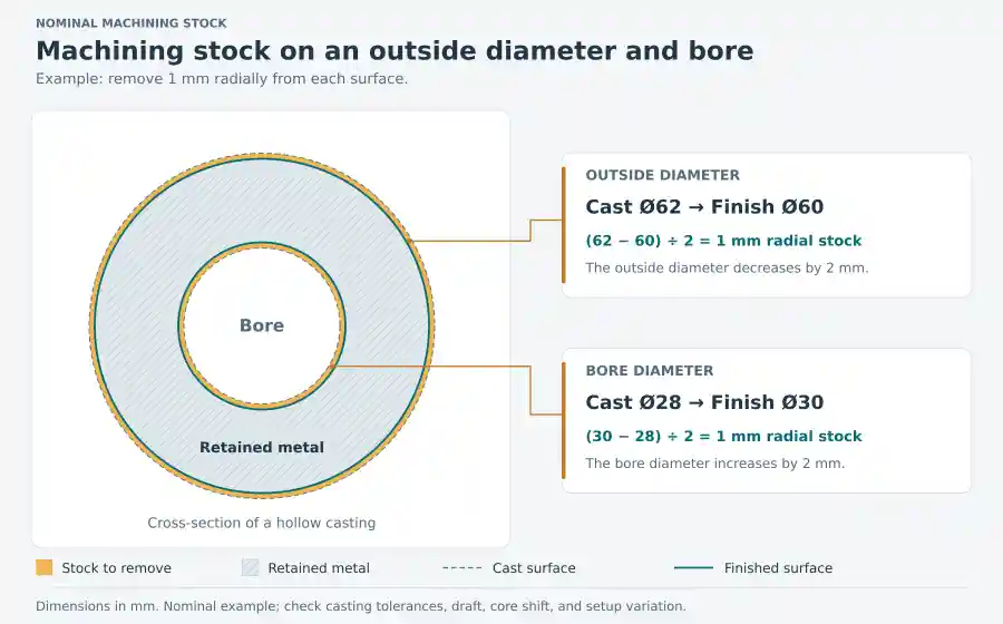
  • Finished outside diameter: 60.00 毫米
  • 成品孔径: 30.00 毫米
  • Nominal machining stock: 1.00 mm per side

The nominal casting dimensions would be:

Cast outside diameter = 60.00 + 2 × 1.00 = 62.00 毫米

Cast bore diameter = 30.00 - 2 × 1.00 = 28.00 毫米

The casting needs a larger outside diameter and a smaller bore because machining removes metal from both surfaces.

Cross-section showing 1 mm radial stock on a 62 mm cast outside diameter and 28 毫米孔径, finished to 60 毫米和 30 毫米.

Now suppose the toolmaker uses an illustrative linear addition of 1.0%, defined relative to the required cold casting dimension.

For the outside feature:

Illustrative pattern dimension = 62.00 × 1.01 = 62.62 毫米

1.0% is an example assumption, not a recommended shrinkage allowance for a particular alloy or casting process.

Check how a supplier defines the percentage. If a shrinkage fraction s is measured relative to the larger tool dimension, the corresponding relationship is:

Tool dimension = required cold casting dimension ÷ (1 − s)

These conventions use different reference dimensions.

Production tooling needs a feature-specific review. Core restraint, 工具温度, 草稿, and trial-casting results may affect the final dimensions. Do not automatically apply the outside-feature calculation to every bore and core.

Check the least stock, not only the nominal stock

The nominal 1.00 mm allowance does not prove that every acceptable casting will clean up.

Assume the same outside feature has:

  • Minimum permitted cast outside diameter: 61.60 毫米
  • Maximum permitted finished outside diameter: 60.05 毫米

For an ideal round casting concentric with the finished feature:

Minimum radial stock = (61.60 - 60.05) ÷ 2 = 0.775 毫米

If this example requires at least 0.80 毫米 to remove the cast surface, the dimensional limits do not provide enough stock—even before other variation is considered.

这里, 0.80 mm is an assumed cleanup requirement for the example, not a universal casting rule.

位置误差, 失真, 表面变化, and setup alignment can reduce local stock further. A shifted cast bore may have excess material on one side and too little on the other.

Draft also changes the available stock along the feature. For a tapered cast bore or boss that will become cylindrical after machining, check the smallest local allowance over the entire machined length. Identify the reference section, draft direction, and machining datums. If the casting model already includes draft, calculate from that geometry without subtracting a second draft allowance.

Draft requirements vary with the surface, 深度, and alloy, as explained in NADCA’s draft guidance. A single assumed angle cannot establish the minimum stock for every casting.

使用 CNC machining tolerance guide to connect these casting limits with the finished dimensions and datum requirements.


Feed the Section That Freezes Last

A section that is still solidifying needs access to enough liquid metal to compensate for its volume change.

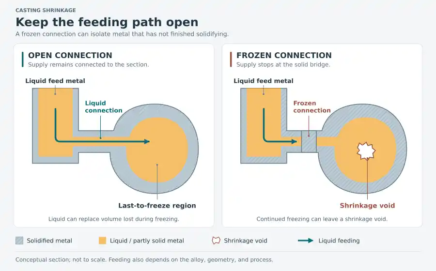
If the connecting path freezes too early, the remaining liquid can become isolated and leave shrinkage voids.

Diagram comparing an open feeding path with a frozen connection that isolates a solidifying casting section.

Researchers studying an A356 aluminum wedge casting used a thin runner that solidified early, cutting off feeding to the wedge. Their observations showed surface sinks developing first, followed by internal shrinkage porosity after the surface became sufficiently rigid. This sequence was documented using real-time X-ray imaging of shrinkage-porosity formation.

For a housing, examine thick bosses, rib intersections, and abrupt wall changes. These features can create regions that cool differently from the surrounding walls. NADCA’s wall-design guidance recommends consistent wall thickness where practical and transitions where thickness must change.

The feeding plan must match the casting process. A sand-casting review may address risers and chills. A high-pressure die-casting review may address gate locations, pressure transmission during freezing, and local die cooling.

Increasing the pattern size alone does not keep a feeding path open.


Check What Machining Will Expose

An acceptable-looking cast surface does not prove that the metal beneath it meets the requirements of a machined sealing face or bearing seat.

Machining may open pores that were previously below the surface. A bore can meet its diameter requirement while exposed pores interrupt its bearing contact area. A face can meet flatness requirements while a connected defect provides a leakage path.

An exposed pore does not automatically mean that a part will leak. Its location, connection to other voids, and relationship to the pressure boundary or sealing area matter.

Adding more machining stock is not a general solution. It increases the material that must be removed and may expose a different region of the casting. Adding stock to the casting design also changes local section thickness, which may affect solidification and feeding.

For a pressure-tight housing, agree on both the required cleanup and the condition of the surface after machining. The stock allowance should be supported by the casting process, sample results, and the specified acceptance tests.

When porosity appears during machining, record the casting batch, affected feature, 地点, and material removed before changing the allowance or toolpath.

Before the first setup, also confirm that gate remnants and flash do not interfere with locating surfaces or extend beyond the stock envelope used in the machining program.


Set Acceptance for the Finished Casting

“Free from shrinkage” is too broad to serve as a practical acceptance requirement.

Define what the finished component must do and how it will be checked:

  • Fits and bearing seats: specify final size, relevant form and location requirements, 表面状况, and the stage at which dimensions apply.
  • Sealing surfaces and pressure boundaries: identify the critical areas and define any leak-test medium, 压力, 期间, 和接受限度.
  • Internal sections: agree on the inspection method, 覆盖范围, and acceptance criteria where internal soundness affects function.
  • Initial samples: check local machining stock and inspect the critical features after the planned material removal.

Visual inspection and liquid penetrant testing cannot rule out enclosed internal void voids. Radiography or another suitable method may be needed when internal discontinuities are part of the acceptance requirement. 这 SFSA overview of nondestructive testing explains the distinction between surface and internal inspection.

The method must suit the alloy, 几何学, defect type, and required sensitivity. A dimensional report does not establish pressure tightness, and an internal inspection result does not replace a specified leak test.

Inspection requirements should be agreed before quotation. 我们的 质量保证流程 provides the basis for discussing dimensional checks and project-specific inspection records; any specialized testing needs separate confirmation.


Review the Casting and Machining Drawings Together

To review a shrinkage or machining-stock problem, share the finished-part drawing together with the proposed casting drawing or model.

Mark the machining datums, surfaces that must fully clean up, 密封面, loaded bosses, and any areas where pores have already appeared. Include the alloy, casting process, 热处理条件, 预期数量, and available dimensional or leak-test results.

These details help determine whether the next change belongs in the tooling compensation, feeding plan, local stock allowance, or machining setup.

Rapid Efficient can review the proposed aluminum die-casting route alongside the CNC machining requirements, and coordinate the casting, 加工, and inspection requirements with the relevant partners before quotation.

发表评论

滚动至顶部

获取报价

点击或拖拽文件到该区域即可上传. 您最多可以上传 10 文件.
文件格式:TXT PDF DOC DOCX XLS XLSX PPT PPTX JPG PNG ZIP RAR DWG DXF DXF DWT DWS DWS

3D文件格式: 步, STP, sldprt, IPT, prt, 坐着, IGES, IGS, catpart, X_T, OBJ, STL