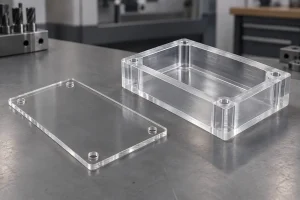
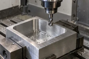
Choosing between a chamfer and a fillet is not mainly a styling decision. On a CNC machined part, edge geometry can determine whether a pin enters cleanly, a shoulder clears its mating component, a cutter can finish a pocket, a burr damages a seal, or an inspector can verify the drawing requirement.
A chamfer creates a flat angled surface between adjoining faces. A fillet creates a rounded transition. However, the right choice depends on where the edge is located and what it must do.
Use a chamfer when the edge needs to guide assembly, provide angled clearance, remove a sharp corner, or create a controlled edge break. Evaluate a fillet or radius when the edge needs a smooth load transition, forms an internal milled corner, or requires a rounded contact or cosmetic surface.
Neither option is universally stronger, cheaper, or easier to inspect. An internal pocket fillet, an external round, a shaft-entry chamfer, and a cosmetic edge may have very different manufacturing requirements.
A Chamfer and a Fillet Do Different Jobs
The first question is not which feature looks cleaner. It is what the edge must do in the finished assembly.
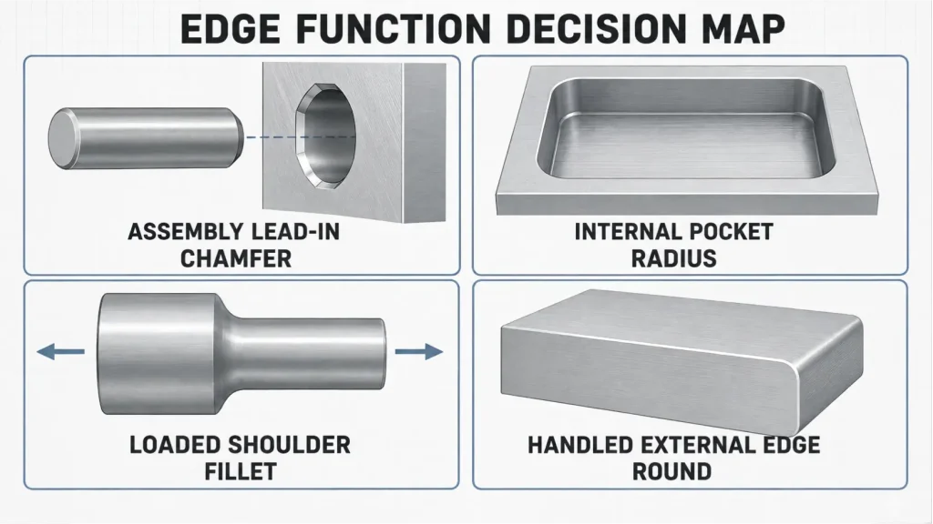
| Functional Need | Usual Starting Point | Main Reason |
|---|---|---|
| Guide a pin, shaft, screw, or bearing into position | Chamfer | Provides an angled lead-in |
| Remove a non-functional sharp edge | Small chamfer or controlled edge break | Simplifies handling and burr removal |
| Reduce an abrupt transition at a loaded internal shoulder | Fillet or radius | Creates a smoother geometric transition |
| Machine an internal pocket corner | Internal radius | A rotating cutter naturally leaves a radius |
| Create a soft external edge | External round | Provides a curved contact or cosmetic surface |
| Clear the radius on a mating component | Chamfer or relief | Prevents premature corner interference |
| Protect a seal as it crosses an edge | Controlled chamfer or radius | Reduces cutting and snagging risk |
These are starting points rather than automatic specifications. Material, available space, loading, mating geometry, machining direction, finishing, and inspection still need to be reviewed.
A chamfer that is too large can reduce bearing area, thread engagement, wall thickness, or sealing length. A fillet that is too small may require a small cutter and long cycle time, while a fillet that is too large may interfere with another component.
Four Edge Conditions That Drawings Often Mix Together
“Chamfer” and “fillet” are sometimes used too broadly. Before comparing them, separate four common edge conditions.
External Edge Chamfer
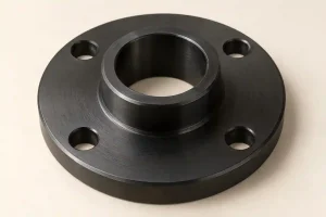
An external chamfer removes a corner with a flat angled cut. A 45-degree chamfer is common, but other angles may be used for assembly, clearance, sealing, or appearance.
Hole or Shaft Lead-In Chamfer
A lead-in chamfer helps a mating component begin entering a hole, bore, thread, bearing seat, or shaft interface. Its angle and length should match the assembly function.
A small hole-edge chamfer should not automatically be treated as a countersink. A countersink is normally a functional conical seat for a fastener head, while a chamfer may only provide an edge break or assembly lead-in.
Internal Fillet
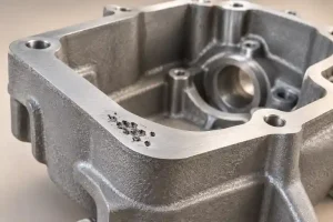
An internal fillet is the concave radius where two surfaces meet inside a pocket, slot, shoulder, or cavity. In milling, this radius is closely connected to cutter diameter, tool reach, and corner engagement.
External Round
A rounded external corner is often called a fillet in CAD software and general discussions. On a manufacturing drawing, “external round” or a clear radius callout can prevent confusion with an internal fillet.
The word “bevel” is also used for angled edges. In general use, it can describe a wider range of sloped surfaces. A manufacturing drawing should therefore control the actual distance, angle, and location rather than depend on the feature name alone.
Use a Chamfer When the Edge Must Guide, Clear, or Break
Chamfers are especially useful when a flat angled transition performs a practical assembly or clearance function.
Assembly Lead-Ins
A chamfer can help align:
- Pins with locating holes
- Shafts with bearings or bushings
- Screws with threaded holes
- Tubes with mating bores
- Press-fit components before engagement
- Components entering an automated assembly fixture
The chamfer should be long enough to provide useful guidance but not so large that it removes a critical amount of contact area.
For a press fit, the lead-in geometry should be reviewed together with the interference, mating length, material, edge condition, and assembly method. A large chamfer can shorten the effective engagement length or create an unexpected local stress condition.
Clearance Between Mating Corners
A chamfer on one component may provide clearance for an internal radius on the mating component. This is common where a shaft shoulder must seat against a part that cannot have a perfectly sharp internal corner.
The designer should confirm that the chamfer clears the mating radius without removing too much bearing surface.
Controlled Edge Breaking
A small chamfer can replace an uncontrolled sharp edge with a measurable feature. This may improve handling and reduce the chance of an edge being damaged during packaging or assembly.
However, “remove sharp edges” and a dimensioned chamfer are not equivalent. The first is mainly a workmanship instruction. The second controls geometry that may affect fit or function.
If a measurable edge break is required, state an allowed range on the drawing rather than relying on a shop default. The range should be selected for the material, wall thickness, mating function, and finishing route.
Seal Entry Edges
A seal that passes across a sharp edge can be cut or scratched. A controlled lead-in chamfer or radius may reduce this risk, but a standard 45-degree chamfer is not automatically suitable for every seal.
Seal material, compression, installation direction, working pressure, surface finish, groove geometry, and the seal supplier’s recommendations should be reviewed before the edge is released.
Internal Fillets Are Also a Cutter-Access Decision
Internal fillets in milled pockets are not merely optional cosmetic additions. A rotating end mill cannot produce a truly sharp internal corner. It leaves a radius related to the cutter and toolpath.
This does not mean that the specified corner radius should simply equal the cutter radius.
When the cutter diameter approaches the full diameter implied by the internal corner, radial engagement can increase sharply as the tool enters the corner. The higher engagement may increase cutting force, vibration, tool deflection, surface marks, and local dimensional error.
A supplier may use a smaller cutter and a programmed corner path to control engagement. The practical strategy depends on:
- Required corner radius
- Pocket depth
- Opening width
- Material hardness
- Tool reach
- Wall rigidity
- Surface finish
- Dimensional tolerance
- Chip evacuation
For suitable pockets, adaptive or trochoidal roughing can keep radial engagement lower while removing bulk stock, and corner slicing or rest milling can address the remaining material. These strategies do not eliminate the need for a smaller finishing cutter or a suitable programmed corner path when the cutter geometry approaches the final part radius.
A small radius in a deep pocket can require a narrow, long-reach tool. That combination may reduce rigidity and require lighter cutting conditions or a separate finishing operation.
Where the design allows it, increasing the internal radius can provide more tool options and reduce corner engagement. The radius still needs to fit the mating component and preserve the required wall or contact geometry.
For broader guidance on pockets, tool access, walls, and internal corners, review the CNC machining design guide.
External rounds behave differently. They may require a corner-rounding cutter, form tool, ball-nose toolpath, turning insert profile, or multi-axis finishing strategy. An external radius is therefore not automatically easier just because an internal radius occurs naturally during pocket milling.
Stress Concentration: Why “Fillets Are Stronger” Is Incomplete
A sharp internal transition can act as a stress raiser. Replacing it with a suitable radius may create a smoother load path and reduce the severity of the geometric discontinuity.
That does not mean every fillet makes every part stronger.
The result depends on:
- Whether the edge lies in the actual load path
- Internal or external edge location
- Radius relative to the surrounding section
- Material and heat-treatment condition
- Load direction
- Static or cyclic loading
- Nearby holes, threads, grooves, and wall changes
- Surface condition
- Available mating clearance
A cosmetic external round may have little effect on a critical internal shoulder. Likewise, a very small radius may not produce the same result as a larger engineered transition.
A chamfer can remove a sharp corner, but it replaces the original corner with two angled transitions. It should not be treated as mechanically equivalent to a smooth radius at a fatigue-critical shoulder.
When structural performance matters, the designer should define the required geometry using engineering calculations, simulation, testing, or applicable design standards. A machining supplier can review manufacturability and inspection, but the final load-bearing requirement remains a design responsibility.
Machining Cost Depends on Where the Feature Is
Chamfers are often described as less expensive than fillets. That can be true for an accessible external edge, but it is not a universal cost rule.
| Feature Condition | Main Machining Consideration | Possible Cost Driver |
|---|---|---|
| Accessible external chamfer | Chamfer mill or programmed toolpath | Additional edge path or tool change |
| Chamfers on several part faces | Multiple orientations may be needed | Additional setups and handling |
| Repeated hole chamfers | Tool height and runout affect consistency | Tool control and inspection time |
| Small internal pocket radius | Requires a smaller cutter | Lower rigidity and longer cycle time |
| Deep internal radius | Requires extended tool reach | Deflection, chatter, and finishing passes |
| External blended fillet | May require a form or ball-nose tool | Additional programming and contour passes |
| Turned shoulder radius | Must match tool and mating clearance | Profile control and insert access |
| Tight chamfer or radius tolerance | More detailed verification is needed | Inspection equipment and reporting |
An internal radius that matches a practical milling strategy may add little separate work. In contrast, a tightly blended external fillet across several faces may require more programming and finishing time than a simple chamfer.
The total cost also depends on how many edges are controlled. Applying an exact chamfer to numerous holes, pockets, and part faces can add significant tool travel and inspection work.
Rapid Efficient’s CNC milling services can support drawing review for internal radii, edge access, burr requirements, surface finish, and inspection before quotation.
Burrs and Surface Finishing Can Change the Final Edge
A CAD model shows nominal geometry. The delivered edge may also be affected by cutting direction, burr formation, manual finishing, polishing, blasting, coating, and handling.
Burrs commonly appear around:
- Drilled and milled holes
- Pocket openings
- Intersecting holes
- Thin walls
- Slots
- Thread starts
- Exit edges
- Small external corners
If a chamfer or radius is functional, manual deburring should not be allowed to define its final size. The geometry should be machined and inspected as a controlled feature.
For non-functional edges, a general edge-break instruction may be sufficient. More information about burr formation and removal is available in this guide to CNC deburring methods.
Finishing can also influence the edge:
- Polishing may blend a small chamfer or round a crisp transition.
- Bead blasting can change the visual contrast between adjacent faces.
- Coating or anodizing may affect dimensional boundaries and inspection timing.
- Masking may be needed around mating, threaded, sealing, or electrical-contact areas.
- Aggressive manual cleanup may change a narrow edge more than a broad surface.
Functional edges should be identified before finishing. The drawing or purchase requirement should state whether the dimension is evaluated before or after the finish when that distinction affects assembly.
Available processes and their dimensional considerations are discussed in the CNC surface finish options.
Dimension the Functional Edge, Not Just the CAD Shape
A 3D model may show the intended feature, but a 2D drawing should identify the dimensions and tolerances that control its function.
Chamfer Callouts
An illustrative chamfer callout may be written as:
0.5 × 45°
This specifies a nominal linear size and angle. It is only an example, not a general recommendation for every edge.
For a non-45-degree chamfer, the drawing may define:
- One linear size and the angle
- Two linear offsets
- The resulting boundary dimensions
- A profile requirement when the geometry is more complex
A shorthand such as “C0.5” may be interpreted differently unless the drawing standard or title block clearly defines it. Providing the actual size and angle reduces uncertainty.
Drawing practices vary among standards, companies, and CAD systems. For cross-border sourcing, identify the governing drawing standard and define both chamfer size and angle when the shorthand is not explicitly controlled by the title block.
Fillet and Round Callouts
A fillet or round is commonly controlled with a radius value and leader, such as:
R2
If the radius affects fit, loading, sealing, or tool access, include an appropriate tolerance and identify the specific edge.
Do not depend on a general “all radii” note when only one radius is functionally critical.
General Edge Notes
A bounded edge-break note may be suitable for non-functional sharp edges. It should not replace separate dimensions for:
- Seal entry edges
- Bearing seats
- Press-fit lead-ins
- Thread starts
- Mating shoulders
- Locating features
- Cosmetic edges with visible requirements
The drawing should also identify burr direction, protected edges, “do not break” edges, and post-finish requirements when relevant.
Inspect the Geometry That Controls Function
Chamfer and fillet inspection should match the feature size, accessibility, tolerance, and required report.
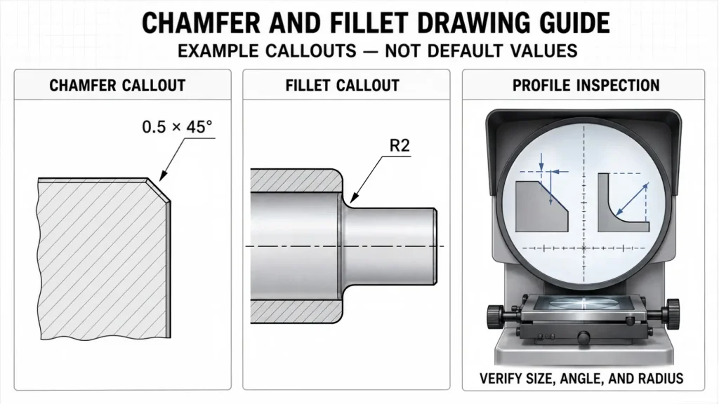
| Geometry | Possible Inspection Method | Important Limitation |
|---|---|---|
| Small accessible chamfer | Chamfer gauge, vision system, or optical comparator | Burrs and part orientation can affect the result |
| Larger chamfer | Linear measurement plus angle verification, optical system, or CMM | Measuring chamfer width alone may not confirm the angle |
| Internal radius | Radius gauge for comparison; optical, contour, or CMM measurement when quantified data is needed | Probe access and point density may limit small-radius evaluation |
| External round | Profile projector, vision system, contour measurement, or CMM | A few points may not represent the complete blended profile |
| Complex 3D blend | CMM or scanned profile comparison with CAD | Datum alignment and accessible surface area matter |
| Assembly lead-in | Dimensional inspection plus functional fit review when appropriate | A passing size does not automatically prove damage-free assembly |
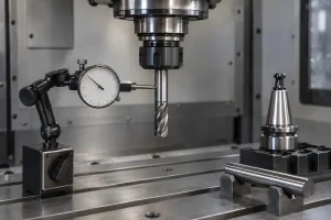
A radius gauge is useful for quick comparison, but it may not provide enough data for a tightly toleranced or reportable profile. Optical and contour measurement can be useful for small chamfers and radii because they evaluate the actual edge profile.
CMM inspection may be appropriate for accessible three-dimensional features, but probe-tip size, access direction, point distribution, and datum alignment should be considered.
The CNC machining tolerances guide explains how material, geometry, datums, feature size, and inspection method affect tolerance planning.
The inspection requirement should answer three questions:
- Is only the nominal edge break important?
- Must the size and angle or radius be reported?
- Does the edge need to pass a functional assembly, sealing, or clearance check?
Chamfer-or-Fillet Decision Matrix for CNC Parts
Use this matrix as a drawing-review tool rather than a fixed design rule.
| Edge Location | Functional Goal | Usual Starting Point | Machining or Design Risk | Drawing and Inspection Need |
|---|---|---|---|---|
| Hole entrance | Guide a pin, screw, or tool | Chamfer | Oversized chamfer may reduce engagement or bearing area | Specify size, angle, and functional diameter |
| Shaft end | Guide a bearing, bushing, or seal | Controlled chamfer or radius | Sharp transition may damage the mating component | Confirm lead-in length, finish, and mating geometry |
| Internal milled pocket | Provide corner clearance | Fillet/internal radius | Small deep radius may require a long-reach cutter | Specify radius and check mating-part clearance |
| Loaded internal shoulder | Smooth the section transition | Engineered fillet | Radius may interfere with the mating face | Define radius from structural and assembly requirements |
| External handled edge | Remove sharpness | Small chamfer or external round | Manual finishing may create inconsistent geometry | General note may be acceptable if the edge is non-functional |
| Mating corner | Clear the other component’s radius | Chamfer or local relief | Excessive removal reduces contact area | Inspect seating and remaining bearing surface |
| Seal-crossing edge | Prevent cutting or snagging | Controlled lead-in chamfer or radius | Generic 45-degree geometry may not suit the seal | Confirm seal specification, finish, burr control, and inspection |
| Cosmetic housing edge | Control appearance and touch | Chamfer or external round | Finishing may alter highlight lines and edge consistency | Define visible faces, finish sequence, and acceptance standard |
| Thread start | Support engagement and remove incomplete sharp edge | Chamfer | Excessive material removal may reduce usable thread | Specify thread depth, chamfer, and first full thread requirement |
| Thin wall or rib edge | Remove sharpness without weakening the feature | Small controlled edge treatment | Large chamfer may create a fragile or undersized wall | Review remaining thickness and inspection access |
The decision should be made feature by feature. A single part may use internal fillets for pocket corners, chamfers for holes and shaft ends, and external rounds on handled surfaces.
Information Needed Before Quotation
A useful edge review requires more than a nominal CAD model. Please provide:
- 3D CAD file
- 2D drawing
- Edge location
- Internal or external geometry
- Functional purpose
- Chamfer size and angle or required radius
- Mating component information
- Load direction or critical transition, when relevant
- Material grade
- Surface finish
- Burr and edge-break requirements
- Inspection method or report requirement
- Order quantity
If the geometry is not finalized, identify what the edge must accomplish: assembly guidance, stress transition, mating clearance, seal protection, safe handling, or cosmetic appearance.
Rapid Efficient can review material behavior, machining strategy, tool access, tolerance risks, edge finishing, inspection, packaging, and delivery requirements before quotation. Structural performance, fatigue life, and seal design should remain tied to the customer’s engineering requirements and applicable validation.