A bore can pass a diameter check and still fail in service. The entrance may be wider than the rest of the hole. The middle may be barrel-shaped. A cross-section may be lobed, or the surface may have the wrong texture for lubrication and sealing. Even a round, smooth bore can have its axis in the wrong position.
The instruction “hone the bore” leaves these problems unresolved. Before choosing the honing process, identify the error, check where material remains, and decide how the finished bore will be inspected.
Quick answer: Conventional rigid honing uses abrasive stones that expand against a pre-machined bore. The tool rotates and moves back and forth along the bore. With enough stock remaining, it can improve diameter, selected form errors, and surface texture. It cannot make an oversized bore smaller. Ordinary floating finish honing generally follows the existing bore axis, so it should not be used as the main operation for correcting position or angle relative to external datums. Specify size, form, datum relationships, and texture separately.
Start With the Bore Error
Measure the incoming bore before choosing the tool. A small, uniform allowance presents a different job from a tapered bore, a wide entrance, or a curved centerline.
The following map applies mainly to conventional rigid honing. Its purpose is to identify which errors may be corrected and what could prevent correction.
| Incoming condition | What honing may correct | Main limit | How to check |
|---|---|---|---|
| Uniformly undersize bore | Bring the diameter toward the final size | Enough removable stock must remain throughout the working length | Diameter readings at several depths and angular positions |
| Taper | Often reduce the diameter change along the bore | The largest section must still leave allowance; stroke and tool contact must suit the error | Diameter map and an axial form trace |
| Bellmouth at an open end | Sometimes reduce the difference between the wide entrance and the smaller bore | The entrance must remain within a size that allows further removal | End-to-center size comparison and form measurement |
| Barrel-shaped bore | Sometimes bring the smaller end regions closer to the middle diameter | The largest middle section must still leave usable allowance | Measurements through the full length and form analysis |
| Lobing or out-of-round sections | Often improve roundness | Tool contact, stone condition, wall stiffness, and allowance limit correction | Roundness traces at defined depths |
| Longitudinal waviness | May reduce selected waves along the wall | Results depend on wavelength, contact length, guidance, and remaining stock | Axial form traces or cylindricity measurement |
| Bow along the bore centerline | Long or guided tooling may improve a curved centerline | This needs a planned correction process; external position and angle still need separate control | Centerline analysis and datum-based inspection |
| Axis position or angle outside tolerance | Generally not a dependable correction with ordinary floating finish honing | Establish the required axis in a suitable datum-controlled operation | CMM or dedicated datum-based gauging |
| Bore already oversize | Cannot restore the original size by honing alone | Further material removal makes the bore larger | Confirm the size before choosing a repair or replacement route |
| Size and form are acceptable, but deglazing or deburring is needed | A suitable flexible abrasive tool may condition the surface or edges | Material removal must not take the bore beyond its size or edge limits | Texture, edge condition, and final size |
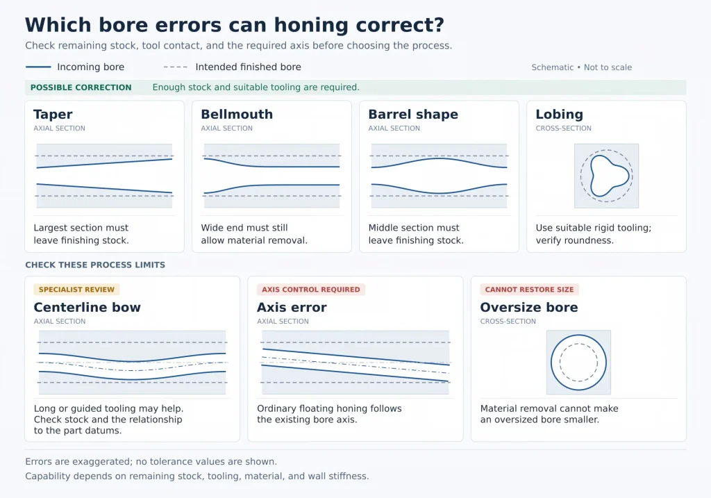
The map identifies possible routes, not guaranteed machine capability. Compare the measured error with the actual material, hardness, bore length, access, tooling, and remaining allowance before approving the operation.
Different Honing Methods Do Different Jobs
The word “honing” covers several tool arrangements and finishing tasks. They should not be treated as interchangeable.
| Method or finishing approach | Main job | Suitable starting condition | Important limit |
|---|---|---|---|
| Rigid long-stroke honing | Control size, selected form errors, and crosshatched texture | A pre-machined bore with enough finishing stock | Does not automatically correct the axis relative to external datums |
| Single-pass honing | Size and finish repeat-production bores, often through a planned tool sequence | Consistent pre-bores and a process developed for the part | Its correction behavior differs from reciprocating long-stroke honing |
| Flexible or brush honing | Deglaze, remove selected burrs, or reduce surface peaks | Size and basic form are already acceptable | Cannot replace rigid honing when meaningful geometry correction is required |
| Line honing | Size related bores and improve their common alignment | Tandem bores with suitable stock, spacing, and tool support | Alignment to external part datums still needs to be specified and checked |
| Plateau honing | Reduce high surface peaks while retaining useful valleys | A defined surface requirement for the sliding or sealing pair | A low Ra value alone does not prove a plateau surface |
Plateau honing describes a surface objective and finishing sequence. It can use rigid or flexible abrasive tools, so it overlaps with the other methods in the table.
A rigid honing tool may also use a floating or jointed mounting arrangement. Rigid abrasive contact does not, by itself, establish the bore axis from the part datums.
For example, a hydraulic sleeve may need rigid honing to correct taper, followed by a separate step to produce the required texture. A bore that only needs cross-hole deburring may need a much lighter abrasive treatment.
Honing Changes Size, Form, and Texture Together
Changing one honing setting can affect bore size, form, and surface texture.
- More dwell in a tight region can remove extra stock, but it also changes local texture and cycle time.
- Rotation and axial stroke create the crossing surface lines. Changing their speed ratio changes the crosshatch angle.
- Abrasive type, bond, grit, stone condition, and honing fluid affect cutting, heat, finish, and tool wear.
- Stone length and guidance affect which form errors the tool can correct.
- Honing pressure and clamping can distort a thin sleeve. Its bore may change after these forces are removed.
A setting chosen to improve Ra may also change diameter. A stroke adjustment made to reduce taper may change the bore ends. Check the other acceptance characteristics after changing the process.
A generic honing surface finish chart cannot define the complete operation. Its values may come from a different material, tool, or measurement method. Use the drawing to define the required result, then select process settings for the actual bore and verify them on suitable parts.
The Incoming Bore Must Leave Correctable Stock
Honing often follows drilling, turning, reaming, grinding, or boring machining. Boring is useful when the axis must first be established from a mounting face, outside diameter, another bore, or the drawing’s datum reference frame.
The allowance is the material left for honing to remove. One nominal allowance does not show whether that material is available around the full circumference and along the working length.
A wide entrance may leave too little stock to remove bellmouth. A deep scratch may require more removal than the size limits allow. An offset pre-bore may extend beyond the intended finished cylinder on one side, even when its measured diameter is undersize. Ordinary floating honing cannot be relied on to recover that datum-related error.
Before honing, check:
- Minimum and maximum incoming diameters at several depths.
- Taper, lobing, waviness, and any centerline bow.
- Remaining allowance after heat treatment, when applicable.
- The operation that establishes the required axis from the datums.
- Later operations that may change the bore, including coating, thermal processing, or press fitting.
- Wall stiffness under clamping and honing forces.
If hardening changes the bore shape, final honing may belong after heat treatment. If a coating forms the working surface, the process must account for coating thickness and whether that coating can be honed. Set the sequence from the part requirements.
State whether the allowance is radial or diametrical. For a concentric circular bore, diametrical allowance is twice radial allowance; mixed conventions can lead to the wrong starting size.
The finished fit also depends on the mating part and inspection state. The CNC machining tolerances guide explains how size, geometry, and processing conditions affect acceptance.
Bore Ends Control the Honing Result
Tool contact changes near an entrance, a through-hole exit, or a blind bottom. These regions often determine whether the full bore can meet the drawing.
In a through-bore, controlled overstroke lets part of the stone move beyond the end of the working surface. Too little or too much overstroke can create uneven removal and form errors. The correct amount depends on stone length, support, and bore geometry.
A blind bore limits travel at one end. A relief groove near the bottom may provide space for the stone to overrun the working surface. The groove must also suit the part’s strength, sealing, and cleanliness requirements.
If a relief is not allowed, special blind-hole tooling, shorter stones, controlled strokes, and suitable fluid delivery may still make honing practical. The supplier must review the required finish length and bottom-corner geometry before quoting.
Extra dwell at the bottom does not automatically solve the problem. Aggressive short strokes can wear the front of the stone unevenly and create a locally enlarged region where those strokes reverse. Check the result along the bore, not only at the bottom.
Relief length and any permitted transition near the bottom should match the actual stone, guide shoes, and mandrel. Do not assign them from a universal groove-width ratio or assume that a blind bore needs a relaxed tolerance without reviewing the tooling.
Short bores may provide too little guidance for a standard tool. Tandem bores add another concern: acceptable individual diameters do not prove a common axis. Where shared alignment matters, evaluate line honing or another suitable guided process.
Crossholes and Interruptions Change Tool Contact
Radial ports, oil grooves, keyways, and slots interrupt the bore wall. As the stone crosses an opening, contact disappears and returns. This can cause abrasive wear, edge damage, or washout—extra material removal around the opening.
Wider stones, wider guide shoes, or suitable multi-stone tooling may help bridge an interruption. The required support depends on opening size and spacing, wall stiffness, stock removal, and tool geometry. A fixed stone-width-to-port-diameter ratio should not become a drawing requirement without process-specific support.
The machining plan should define:
- Whether crossholes are made before or after final honing.
- How the tool crosses each opening without catching or losing support.
- The allowed edge break and limits on port enlargement.
- How burrs, chips, and loose abrasive are removed from intersecting passages.
- Which openings need local inspection after finishing.
If a crosshole is drilled after honing, its breakthrough burr may damage the finished bore. If it is drilled first, the honing tool must handle interrupted contact. Choose the sequence for the feature and its function.
A flexible tool can help with cross-hole deburring when bore size and form are already acceptable. It should not replace a rigid process intended to correct taper or roundness.
Sunnen provides separate honing technical guides for blind holes, interrupted bores, and tandem bores. These are useful references when reviewing tool contact and access for a specific part.
Crosshatch and Plateau Texture Must Match the Function
The rotating and reciprocating tool produces crossing lines on the bore wall. Their angle depends on rotational surface speed and axial stroke speed.
A hydraulic seal, sliding spool, engine cylinder, and static locating sleeve have different surface requirements. There is no single crosshatch angle that suits every application.
When angle matters, specify its permitted range and how it is measured. State whether the angle is measured from the bore axis or between the crossing lines. Those conventions give different numbers for the same surface.
Ra alone may hide important differences. Surfaces with similar Ra can have different peak heights, valley structures, waviness, or isolated scratches. These differences can affect running-in, lubrication, and sealing.
Plateau honing reduces high peaks while retaining useful valleys. Where the function requires more than Ra, the specification may include parameters from the material-ratio curve:
- Rpk: reduced peak height, describing the upper peak region.
- Rk: core roughness depth, describing the central region of the profile.
- Rvk: reduced valley depth, describing the lower valley region.
Define the applicable standard, filtering, evaluation length, trace direction, and acceptance limits. These parameters describe the surface; they do not independently prove sealing performance.
ISO 21920-2:2021 defines profile surface-texture terms and parameters and replaces the withdrawn ISO 13565-2:1996. For an existing drawing, confirm the specified edition before changing how the surface is measured.
Our guide to surface finish requirements for CNC-machined parts covers the broader drawing requirements. For honed bores, also inspect for torn or folded metal, deep scratches, embedded abrasive, and areas that the tool has not fully cleaned up.
One Bore Needs Four Separate Acceptance Questions
Each acceptance question needs a drawing requirement and a suitable measurement method.
| Acceptance question | What to specify | Why diameter alone is insufficient | Suitable evidence |
|---|---|---|---|
| Is the bore the correct size? | Diameter limits, fit, measurement temperature, and whether coating is included | One reading misses variation along the length or around the bore | Calibrated size readings at defined depths and angular positions |
| Is the bore the correct form? | Roundness, straightness, cylindricity, or other form limits required by function | Local size can pass while the bore remains lobed, tapered, bowed, or bell-mouthed | Form traces or an agreed measurement map with suitable coverage |
| Is the axis in the correct position and direction? | Datums and the required position, orientation, or relationship to other features | Good internal form does not establish the axis relationship to the part | Datum-based CMM or dedicated functional gauging |
| Is the surface suitable for its job? | Roughness parameters, lay or crosshatch, plateau requirements, and cleanliness | A size reading says nothing about peaks, valleys, scratches, or residue | Texture traces, specified angle checks, and surface and cleanliness inspection |
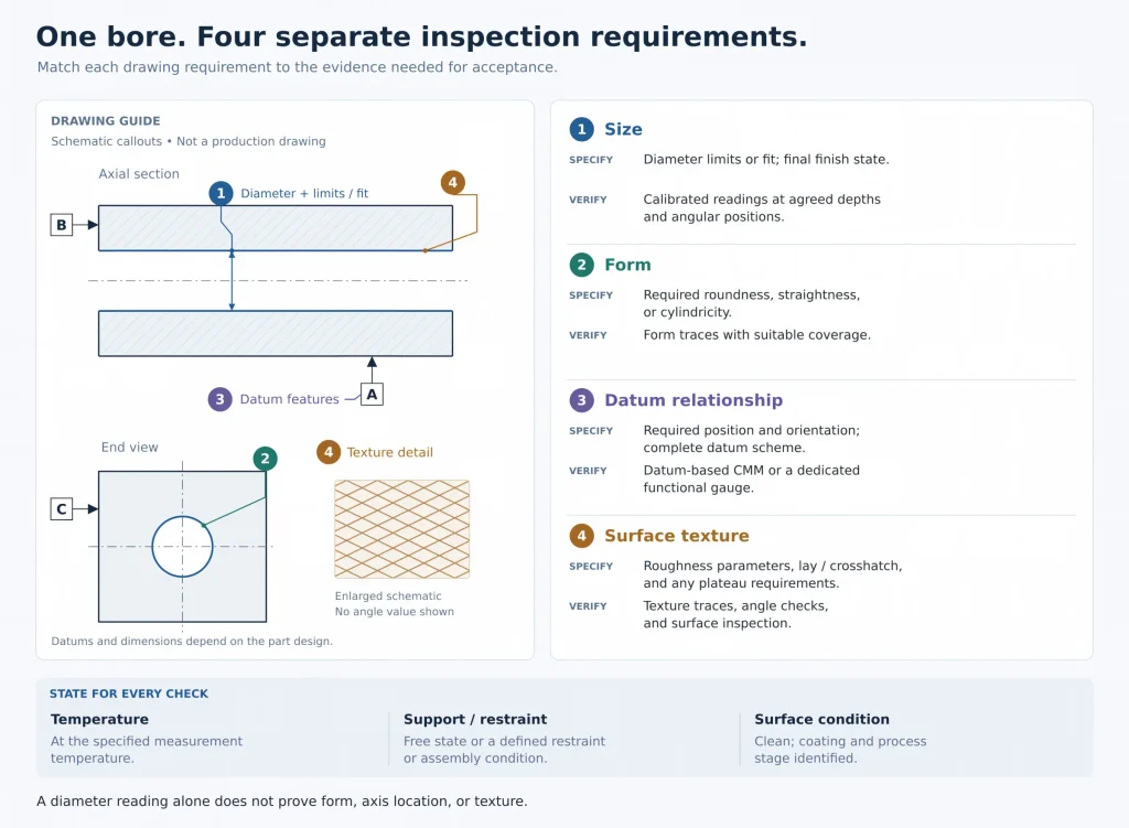
Agree on these requirements before production. This lets the machinist and inspector work toward the same acceptance result.
For thin sleeves or assembled housings, also state whether these checks apply in the free state or under a defined restraint or assembly condition. A bore measured while clamped may change after release.
Measure the Error You Asked Honing to Correct
A plug gauge can provide a useful limit or functional check, depending on its design. It does not provide a detailed map of taper, lobing, or axis location.
A two-point bore gauge compares diameter at selected depths and angular positions. It can reveal some size changes, but certain lobed forms may escape a two-point check. Do not present a few diameter readings as complete roundness verification.
Air gauging can support fast repeat checks. Its response depends on the jet arrangement, circuit, masters, and measurement procedure. A setup designed only for diameter does not prove every form or datum requirement.
When roundness or cylindricity controls function, use suitable form measurement with enough sectional and axial coverage. When the concern is bore position or angle, use datum-based inspection. The CMM inspection guide explains why alignment, probe access, and sampling must match the characteristic being reported.
Surface texture needs its own measurement setup. Stylus geometry, trace direction, filtering, evaluation length, and trace location can change the result. Crosshatch angle may need controlled imaging. Clean the part and let it reach the specified inspection temperature before acceptance measurements.
Production gauges can shorten each check, but dedicated air plugs, masters, fixtures, and calibration add setup cost. Detailed form and texture measurements may require more inspection time. Select the methods and sampling frequency from feature risk, process capability, customer requirements, and production volume.
A useful first article inspection can establish the incoming bore condition, final size map, required form traces, datum relationships, and texture results. Routine production checks can then follow the agreed control plan. There is no universal inspection time or sampling count that suits every honed bore.
Four Decisions Set the Route Before Quotation
Use the following questions to decide whether honing belongs in the process and what it must achieve.
| Decision | If yes | If no |
|---|---|---|
| Does enough stock remain where correction is needed? | Compare the measured allowance with the proposed tool and correction | Resolve the oversize or missing-stock condition before approving honing |
| Does the plan include control and verification of the required axis? | Review the datum-controlled operation and protect that relationship through finishing | Add a suitable axis-control operation or evaluate a specialist guided route |
| Is the remaining task only surface or edge conditioning? | Evaluate a suitable finishing tool while protecting size and edge limits | Select rigid or specialist tooling for the required geometry correction |
| Are form and functional texture both specified? | Plan the abrasive sequence and inspection for both | Check whether the missing requirement matters to function before adding it |
These decisions help prevent a supplier from quoting a light surface treatment for a bore that needs geometry correction, or quoting honing for an axis error that belongs to another operation.
Review the Incoming Bore Before Quotation
Send enough information to compare the starting bore with the required finished result:
- Material grade, condition, and final hardness.
- Incoming bore process, measured size range, and known form errors.
- Final diameter, fit, geometric tolerances, and datum scheme.
- Bore length, wall thickness, and through-hole or blind-hole geometry.
- Reliefs, shoulders, ports, grooves, keyways, and crossholes.
- Heat-treatment, coating, assembly, and cleaning sequence.
- Surface-texture parameters, crosshatch or plateau requirements, and applicable standards.
- Inspection state, required reports, sampling requirements, and production quantity.
- Mating component, lubrication, seal, and load conditions that affect the bore.
Submit the drawing, CAD model, and incoming bore measurements through our precision machining services page. Rapid Efficient can review the pre-hone allowance, datum requirements, tool access, surface specification, and inspection plan before quotation.
The review can identify whether the part needs specialist ID honing, line honing, a different finishing process, or an earlier operation to establish the axis. This gives the quotation a clear scope: the error to correct, the surface to produce, and the evidence required for acceptance.