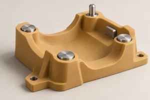
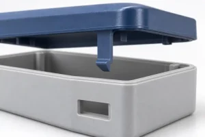
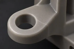
Die casting and injection molding use the same broad manufacturing idea: material enters a reusable metal tool under pressure and takes the shape of a cavity. That similarity can be misleading.
Choose die casting when the finished component must continue behaving like a metal part—for example, when the design depends on structural stiffness, heat transfer, electrical continuity, durable threaded joints, dimensional stability at temperature, or a stiff, low-creep load path under sustained assembly preload.
Choose injection molding when polymer behavior is acceptable or desirable, including electrical insulation, low mass, corrosion resistance, integrated clips, molded color and texture, controlled flexibility, or the consolidation of several assembly features.
When both material families could satisfy the product, the decision should be based on how the geometry must change, where process variation appears, which features need secondary operations, how mature the design is, and what the accepted parts will cost over the program lifetime.
Sending one unchanged CAD model to a die caster and an injection molder and then selecting the lower quotation is not a reliable comparison. The same functional product normally needs two different production designs.
In this guide, die casting means high-pressure die casting of nonferrous alloys, especially aluminum, zinc, and magnesium. Injection molding means thermoplastic injection molding. The comparison does not cover metal injection molding, gravity casting, thermoset molding, or liquid silicone rubber molding.
Start With the Function the Material Cannot Lose
The material decision must come before detailed tooling optimization.
A die-cast alloy may be the starting direction when the part must provide:
- A metallic heat path or heat-spreading surface.
- Electrical grounding or electromagnetic shielding continuity.
- High stiffness within a restricted package.
- Durable bearing, locating, or threaded interfaces.
- A low-creep structural load path under sustained fastener preload at the specified temperature.
- A metallic exterior or structural load path.
Injection molding may be the stronger direction when the part benefits from:
- Electrical insulation.
- Reduced mass.
- Integrated snap fits, clips, cable guides, and compliant assembly features.
- Molded color, grain, texture, or identification details.
- Resistance to environmental corrosion without a metallic coating.
- Controlled flexibility or impact response.
- Consolidation of multiple nonstructural components.
These are starting directions, not universal rules. Filled engineering polymers can close part of the stiffness or temperature gap, while different die-casting alloys provide substantially different mechanical, thermal, and finishing behavior.
Convert every material preference into a service requirement:
- Operating and peak temperature.
- Static, cyclic, and impact loads.
- Permitted creep or clamp-load loss.
- Heat-transfer and grounding requirements.
- Chemical, UV, flame, and moisture exposure.
- Seal pressure and permitted leakage.
- Assembly torque and service cycles.
- Cosmetic zones and permitted process marks.
If these requirements have not been resolved, use the aluminum and plastic part selection guide before comparing the two molding processes. This article begins at the next decision: how an approved metal or polymer direction changes the production design.
The Same CAD Model Must Become Two Different Designs
A machined prototype may use thick walls, sharp internal transitions, deep pockets, and tapped holes because material is removed from solid stock. Tool-based production requires a different logic.
The following matrix shows how the same requirement usually creates two different design responses.
| Functional requirement | Die-cast design response | Injection-molded design response | Dangerous cross-process shortcut |
|---|---|---|---|
| Main walls | Maintain flow-compatible sections and avoid isolated heavy masses that create hot spots and difficult solidification | Maintain controlled nominal walls and core out heavy sections to manage shrinkage and cooling | Retaining the machined wall thickness and only changing the material |
| Structural stiffness | Use section depth, ribs, alloy stiffness, curvature, and local metal distribution | Use rib networks, box sections, curvature, gussets, and appropriate resin stiffness | Making the polymer wall uniformly thick to imitate metal stiffness |
| Ribs | Balance stiffness with metal flow, die filling, ejection, and local thermal mass | Size and position ribs to reduce sink, read-through, differential shrinkage, and warpage | Copying identical rib thickness and spacing into both tools |
| Fastener bosses | Review boss feeding, local mass, cored holes, machining access, and thread load | Support bosses with ribs or gussets and choose between self-tapping screws, molded threads, or inserts | Copying a tall isolated metal boss into the polymer design |
| Threads | Form, machine, tap, or insert the thread according to accuracy, load, service, and alloy behavior | Use molded threads, thread-forming screws, installed inserts, insert molding, or compression limiters as required | Assuming a nominal thread callout defines the production method |
| Draft and ejection | Coordinate draft with die opening, parting, slides, ejectors, surface finish, and distortion risk | Coordinate draft with shrinkage, texture, core retention, ejector placement, and cosmetic surfaces | Applying one draft scheme to both tools |
| Undercuts | Use movable cores, slides, design changes, or secondary machining after reviewing die access and flash | Use side actions, lifters, collapsible features, inserts, or material flexibility when appropriate | Assuming an undercut feasible in one process has the same tool cost in the other |
| Heat and EMI functions | Preserve conductive paths and define how coatings, joints, and fasteners affect them | Add conductive materials, coatings, inserts, heat spreaders, or a separate metal chassis if required | Expecting a polymer substitution to preserve an unspecified metal function |
| Sealing interfaces | Review porosity risk, machining stock, final flatness, roughness, coating, and leak validation | Review molded flatness, shrinkage, warpage, material creep, chemical exposure, and gasket compression | Reusing the same gasket land and bolt preload without recalculation |
| Critical datums | Decide which features remain as-cast and which are created by secondary machining | Relate critical dimensions to fixed cavity features, moving cores, inserts, and conditioned part state | Applying one general tolerance block to every feature |
| Cosmetic surfaces | Account for parting lines, overflows, ejector marks, trimming, polishing, blasting, plating, or coating | Account for gate vestige, weld lines, ejector marks, texture, gloss, color, and fiber read-through | Assuming one appearance specification describes both surfaces |
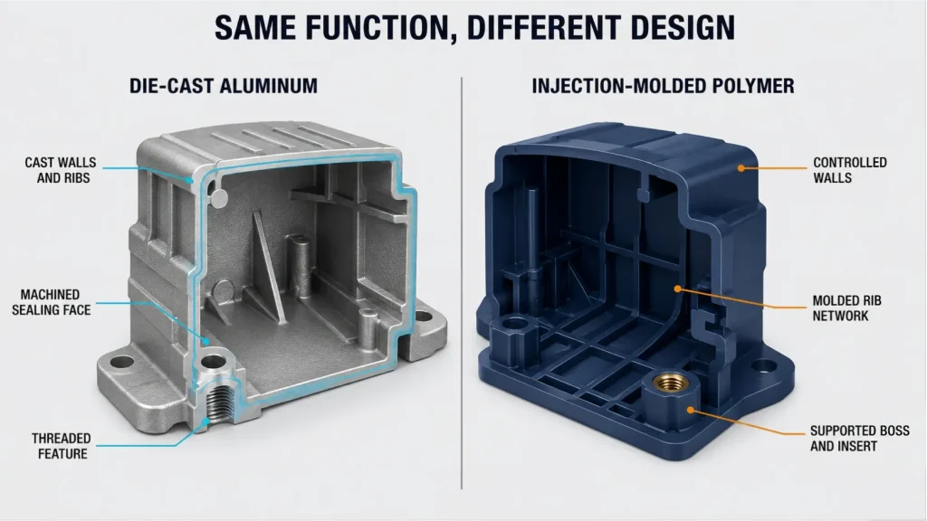
The important point is not that one geometry is more complex. It is that the geometry must move risk away from what each process controls poorly and toward what it controls well.
A valid comparison therefore requires two DFM concepts:
- A die-cast version designed around metal flow, solidification, ejection, trimming, and possible machining.
- An injection-molded version designed around polymer flow, shrinkage, cooling, orientation, ejection, and assembly behavior.
Only after those concepts exist can tooling and unit-cost quotations be compared fairly.
Metal Flow and Polymer Flow Leave Different Evidence
Both processes fill a cavity, but their defect mechanisms and inspection evidence are different.
What happens in die casting
Molten metal enters the die rapidly and begins solidifying against the tool surfaces. Gate design, runner balance, overflow placement, venting, vacuum assistance where applicable, die temperature, local section mass, and ejection timing interact.
NADCA’s die-casting overview connects uniform wall design, draft, fillets, metal flow, venting, cooling, and ejection as related die-design considerations.
Depending on the alloy, geometry, tool, and process, relevant risks can include:
- Entrapped gas or oxide films.
- Local shrinkage porosity.
- Cold shuts or incomplete filling.
- Flash at parting lines and moving components.
- Distortion during solidification, trimming, or ejection.
- Subsurface porosity exposed by later machining.
A visually sound casting is not automatically pressure-tight. A sealing or fluid-handling component needs a leak requirement and an inspection method appropriate to its actual service condition.
Secondary machining also changes the evidence. Cutting through the original cast skin may expose internal discontinuities that were not visible on the unmachined surface.
What happens in injection molding
Thermoplastic melt fills the cavity and begins freezing at the mold wall. Packing pressure compensates for part of the material shrinkage until the gate freezes, while cooling history and molecular or fiber orientation influence the released shape.
BASF’s molded-part analysis shows why local material masses, screw-fixture geometry, undercuts, and gate location can affect pressure, shrinkage, warpage, and fiber orientation.
Relevant injection-molding risks can include:
- Differential shrinkage and warpage.
- Sink marks or internal voids around heavy sections.
- Short shots and trapped-air burns.
- Weld or knit lines where flow fronts meet.
- Flash at parting lines and movable components.
- Gate-related orientation or cosmetic defects.
- Direction-dependent shrinkage and strength in fiber-filled materials.
A gate relocation is not merely a cosmetic change. It can change filling pressure, flow-front meeting locations, fiber orientation, dimensional movement, and the load path through the finished component.
| Production evidence | Die casting | Injection molding |
|---|---|---|
| Heavy local section | Hot spot, slow solidification, shrinkage or porosity risk | Slow cooling, sink, void, cycle-time and warpage risk |
| Meeting flow fronts | Cold shut or oxide-related discontinuity may require review | Weld-line appearance and mechanical performance may require review |
| Parting or side action | Flash, mismatch, trimming access, and local tolerance effects | Flash, mismatch, witness lines, and local tolerance effects |
| Secondary material removal | May reveal subsurface porosity or alter the datum structure | May expose fibers, remove a molded surface, or introduce local stress |
| Released-part shape | Influenced by solidification, trimming, residual stress, and machining | Influenced by shrinkage, cooling balance, orientation, and conditioning |
Neither process is universally more accurate or more defect-free. Each one produces a different risk map.
Threads, Seals, and Precision Features Reveal the Real Route
Every critical feature needs an owner. It must be created by the die or mold, a replaceable tool insert, a secondary machining operation, an installed component, or the final assembly.
Leaving that ownership undecided produces quotations that look comparable but include different assumptions.
Threads and assembly preload
A die-cast design may use a cast boss, a cored pilot hole, a machined and tapped hole, or a threaded insert. The correct route depends on thread size, alloy, engagement, repeated assembly, preload, positional accuracy, coating, and available machining access.
An injection-molded design may use:
- A thread-forming screw and molded boss.
- A molded thread.
- A heat-installed or ultrasonically installed insert.
- An insert-molded metal component.
- A through-bolt with a nut.
- A compression limiter where clamp load must bypass the polymer.
A metal insert does not automatically solve the joint. Boss geometry, insert installation, wall support, service temperature, assembly torque, polymer creep, and crack-sensitive chemicals must still be reviewed.
Sealing and pressure boundaries
For a die-cast housing, the sealing plan may include a machined gasket land, groove, threaded port, or locating bore. The final assessment should address:
- Porosity-sensitive regions.
- Machining depth and stock.
- Final flatness and surface texture.
- Coating or conversion treatment.
- Fastener pattern and preload.
- Leak-test medium, pressure, duration, and acceptance criterion.
For an injection-molded housing, a sealing surface may be produced directly by the mold, but the released geometry can still be affected by shrinkage, rib placement, gate position, cooling balance, moisture conditioning, and assembly load.
Long-term polymer creep can also reduce gasket compression. A seal that passes immediately after assembly may require additional validation after temperature exposure or sustained clamp load.
Locating, bearing, and alignment features
A die casting may use secondary machining to establish bearing bores, threaded patterns, sealing planes, or final locating datums after trimming, using a datum scheme defined for the machining setup.
An injection-molded component may locate directly from molded features, use tool inserts for critical geometry, or incorporate metallic bushings and locating sleeves.
Critical requirements should never be hidden inside a broad title-block tolerance. State which feature establishes the datum, which process creates it, and in what condition the part will be inspected.
A Tight Tolerance Does Not Cost the Same in Both Routes
Tolerance difficulty is not determined by the nominal value alone.
A dimension contained within one fixed die or mold member is different from a dimension that crosses:
- A parting line.
- A moving slide or lifter.
- Two separate tool inserts.
- A trimming operation.
- A secondary machining setup.
- A polymer weld line or orientation transition.
- A large region affected by released-part warpage.
For die casting, the tolerance strategy should distinguish as-cast geometry from machined final features. Critical machining stock, datum transfer, casting movement, fixture location, coating allowance, and inspection state all affect the final result.
For injection molding, dimensional capability depends on resin grade, filler orientation, shrinkage behavior, cavity location, gate and packing conditions, cooling balance, tool temperature, part ejection, and post-molding conditioning.
Before applying a tight tolerance, ask:
- Does the dimension directly protect fit, sealing, motion, or alignment?
- Which die, mold, slide, insert, or machining operation creates it?
- Does it cross a parting line or moving component?
- Is it measured as-cast, as-molded, after machining, after finishing, or after conditioning?
- What temperature and support condition apply during inspection?
- Could a functional gauge replace several isolated coordinate tolerances?
- Is process capability required, or only individual-part conformance?
When secondary machining is part of the route, the CNC machining tolerances guide helps separate functional machining requirements from the broader casting or molding tolerance structure.
A catalog tolerance table cannot prove that a specific feature will remain capable in a specific tool. Capability must be related to the actual geometry, material, tool layout, processing window, and inspection method.
Tooling Cost Is a Commitment to a Frozen Design
Both processes can support high production volumes, but tooling cost is more than the quoted price of the primary mold or die.
A die-casting tooling package may involve:
- Die blocks and cavity inserts.
- Fixed and moving cores.
- Slides and replaceable wear components.
- Runner, gate, overflow, and vent systems.
- Cooling circuits and ejectors.
- Trimming or secondary fixtures.
- Machining, leak-testing, and inspection fixtures.
An injection-molding tooling package may involve:
- Cavity and core construction.
- Cold-runner or hot-runner systems.
- Slides, lifters, inserts, and unscrewing mechanisms.
- Cooling circuits and ejection systems.
- Texture, polishing, and cosmetic controls.
- Insert-loading or post-molding automation.
- Inspection and assembly fixtures.
Tooling therefore commits the product to a material family, shrinkage assumption, parting strategy, gate system, ejection layout, and feature architecture.
A design change made before tooling release may require only CAD work. The same change after steel has been cut may require welding, insert replacement, slide modification, retexturing, revalidation, or an entirely new tool.
There is no universal production quantity at which die casting or injection molding automatically becomes cheaper. A more useful comparison is:
Lifetime unit cost = (tooling + tool changes + validation + maintenance) ÷ accepted lifetime quantity + part production + secondary operations + inspection + quality risk + assembly
“Accepted lifetime quantity” matters more than forecast quantity. Scrap, variants, engineering changes, spare tooling, maintenance interruptions, and end-of-life demand can change the denominator.
The quotation should therefore identify:
- Annual and lifetime quantity.
- Number of product variants.
- Expected design-freeze date.
- Tool ownership and maintenance responsibility.
- Planned tool life and replaceable components.
- Sampling and approval stages.
- Secondary machining and finishing.
- Inspection and process-capability requirements.
- Packaging and assembly scope.
For the polymer route, these decisions should be resolved before releasing injection mold tooling services, because late changes may affect more than the visible cavity geometry.
Prototype Evidence Is Process-Specific
A CNC-machined or 3D-printed prototype can answer valuable questions:
- Does the part fit the assembly?
- Are connectors, fasteners, tools, and hands able to reach the required areas?
- Does the envelope interfere with neighboring parts?
- Is the approximate stiffness or mass acceptable?
- Does the initial thermal or electrical concept work?
- Can the product be assembled and serviced?
It cannot fully reproduce production-process evidence.
A machined aluminum prototype does not reveal die-casting porosity, flow-front behavior, trimming distortion, gate vestige, ejector marks, or the effect of machining through a cast surface.
A machined or printed polymer prototype does not automatically reproduce molded shrinkage, weld lines, fiber orientation, gate-related stress, surface texture, ejector evidence, or the production resin’s conditioned behavior.
| Validation question | Die-cast sampling should consider | Injection-molded sampling should consider |
|---|---|---|
| Filling evidence | Incomplete fill, cold shuts, overflow and vent behavior, flash, porosity-sensitive areas | Short shots, burns, weld lines, gate performance, flash, and packing response |
| Released dimensions | Shape after ejection, trimming, stabilization, machining, and specified finishing | Shape after ejection, cooling, conditioning, insert installation, and specified finishing |
| Critical interfaces | Machined datums, sealing faces, threads, bores, coating, and leak performance | Bosses, inserts, snap fits, seals, warpage, creep-sensitive joints, and cosmetic zones |
| Surface acceptance | Parting lines, ejector marks, trimming, machining witness, blasting, plating, or coating | Gate vestige, ejector marks, texture, gloss, color, sink, weld lines, and fiber read-through |
| Functional testing | Load, torque, thermal path, grounding, pressure integrity, and assembly fit as applicable | Load, torque, insert retention, snap cycles, chemical compatibility, creep, and assembly fit as applicable |
Not every project needs every test. The verification plan should be selected from the actual failure consequences.
A first sample is also not proof of a stable production process. Approval should use the intended material, the intended tool configuration, the required secondary operations, and an agreed inspection condition.
Use Two RFQs, Not One Neutral Drawing
The functional requirements can be shared, but each process needs its own manufacturing definition.
| RFQ field | Die-casting RFQ must define | Injection-molding RFQ must define |
|---|---|---|
| Material | Alloy designation, required properties, finishing condition, and any pressure-integrity requirement | Exact resin grade, filler, color, UV or flame requirement, conditioning state, and regrind restrictions if applicable |
| Functional priorities | Stiffness, thermal path, grounding, structural load, sealing, threads, and service temperature | Insulation, mass, flexibility, creep limit, snap behavior, chemicals, appearance, and service temperature |
| Tool-dependent evidence | Acceptable parting lines, gates, overflows, ejector marks, trimming, slides, and core locations | Acceptable gates, weld lines, ejector marks, parting lines, slides, lifters, texture, and core locations |
| Precision features | As-cast versus machined dimensions, machining stock, datum transfer, and final inspection state | Molded dimensions, moving-core relationships, insert locations, shrinkage assumptions, and conditioned inspection state |
| Threads and inserts | Cast, cored, tapped, machined, or inserted thread route | Molded thread, thread-forming screw, installed insert, insert molding, through-bolt, or compression limiter |
| Sealing | Porosity-sensitive zones, machining, surface texture, coating, leak medium, test pressure, and acceptance | Gasket land, warpage, surface texture, clamp load, creep, chemical exposure, and conditioned state |
| Secondary work | Trimming, deburring, machining, blasting, coating, plating, impregnation, assembly, and inspection as required | Degating, insert installation, decoration, coating, welding, assembly, conditioning, and inspection as required |
| Appearance | Cosmetic zones and acceptable parting, flow, trimming, ejector, machining, and finishing evidence | Cosmetic zones and acceptable gate, weld-line, sink, ejector, gloss, color, and texture variation |
| Quality evidence | Sampling stage, dimensional report, functional testing, leak testing, material evidence, and capability requirements | Sampling stage, dimensional report, functional testing, resin evidence, appearance standard, and capability requirements |
| Commercial assumptions | Annual and lifetime volume, variants, tool life, maintenance, spare inserts, design changes, and ownership | Annual and lifetime volume, cavities, variants, tool life, maintenance, design changes, automation, and ownership |
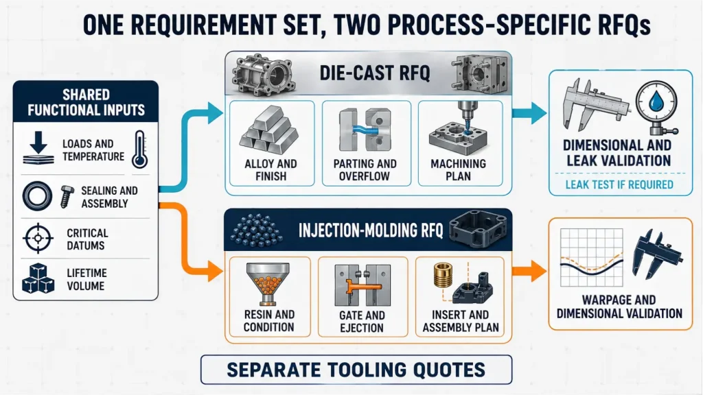
A supplier cannot resolve these decisions from a generic STEP file alone.
The model should be accompanied by a drawing or controlled requirement document that identifies the critical functions, permitted process evidence, final inspection state, and validation responsibilities.
Two process-specific RFQs may produce two substantially different geometries. That is a sign of a valid comparison—not a failure to quote the original model consistently.
Decision: Choose the Production Risk You Can Control
Choose die casting as the starting route when:
- The product must retain metallic stiffness, heat transfer, grounding, shielding, or durable load-bearing interfaces.
- Secondary machining can economically establish the critical datums, bores, sealing faces, and threads.
- The team can control metal flow, solidification, porosity-sensitive regions, trimming, and finishing.
- The expected volume and design maturity justify the tooling commitment.
Choose injection molding as the starting route when:
- The product can meet its service requirements with a thermoplastic resin.
- Low mass, insulation, integrated clips, molded texture, corrosion resistance, or component consolidation provides meaningful value.
- The team can redesign the part around controlled walls, polymer flow, shrinkage, cooling, creep, and assembly behavior.
- The expected volume and design maturity justify the mold and validation plan.
Consider a hybrid architecture when neither material should perform every function. Examples include:
- A die-cast chassis with an injection-molded cover.
- A polymer housing with a metal heat spreader.
- A molded component with threaded or locating inserts.
- A die-cast structural frame carrying polymer cable guides, seals, or insulating features.
The final decision should not ask, “Which process is better?” It should ask:
Which material must perform each function, which process can create the required geometry, and which production risks can be measured and controlled?
For a useful manufacturing review, provide the 3D model and drawing together with material candidates, annual and lifetime volume, critical datums, assembly torque, sealing requirements, thermal or electrical functions, cosmetic zones, and the intended validation state.
RapidEfficient can then review the applicable route through its aluminum die casting services or injection molding services before production tooling is released.