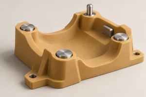
A datum target is a specified point, line, or limited area used to establish a datum when contact with an entire surface would be unstable, nonfunctional, or difficult to reproduce. Datum targets work only when the drawing, manufacturing setup, and inspection method create the same intended contact and restraint.
This article explains how target sets establish a reference, why point, line, and area targets are not interchangeable, and what designers, machinists, and inspectors must agree before a part is quoted or accepted. The examples use ASME Y14.5-2018 (R2024) terminology unless the drawing states another standard; an ISO 5459 drawing should be interpreted under the ISO edition specified on the product definition rather than silently mixed with ASME practice.
A Datum Target Selects Contact; It Does Not Replace the Datum
A datum is a theoretically exact reference. The datum target identifies a controlled portion of the actual part from which that reference is established.
The target is therefore not the datum itself, and it is not automatically a physical mark machined into the component. It is an instruction telling the fixture, gauge, or mathematical inspection process where and how the part is to participate in datum establishment.
| Term | What It Means | What Production Must Reproduce |
|---|---|---|
| Datum | A theoretically exact point, axis, line, or plane | The reference required by the drawing |
| Datum feature | The actual part feature associated with the datum | The correct surface or feature in the required condition |
| Datum target | A specified point, line, or limited area on the part | The designated contact location and contact form |
| Datum target set | The targets grouped under one datum letter, such as A1, A2, and A3 | The complete set and its intended precedence |
| Datum feature simulator | The physical or mathematical counterpart used to establish the datum | Contact geometry, direction, sequence, and restraint consistent with the drawing |
For broader background on datum features, primary-secondary-tertiary precedence, and work-coordinate transfer, review our guide to types of CNC machining datums.
Datum targets are useful when a complete surface is rough, bowed, interrupted, flexible, very large, or unrelated to the real assembly contact. Typical candidates include castings, forgings, molded parts, stampings, weldments, large panels, and thin structures. A rigid machined face may also use targets when the functional interface contacts only defined pads rather than the entire face.
The opposite is equally important: datum targets do not automatically improve a sound datum scheme. If a stable, accessible, functional surface is intended to contact its mate over the full face, replacing it with arbitrary target patches can create a reference that is repeatable but functionally wrong.
Read the Target Frame as an Instruction to Build Contact
Under common ASME drawing practice, a datum target frame is a circle divided by a horizontal line. The lower compartment identifies the datum letter and target number, such as A1. The upper compartment carries target-size information when applicable. The target location, orientation, side of the part, and extent must be read together with the associated views and dimensions.
Point, line, and area targets describe different interfaces:
| Target Type | Intended Contact | Possible Simulation | Drawing Information That Matters | Main Misinterpretation Risk |
|---|---|---|---|---|
| Point target | One specified local contact | A suitable spherical-ended locator or a corresponding mathematical contact | Basic location, surface side, contact direction, and target ID | Treating any nearby probe hit as equivalent |
| Line target | Contact along a specified line or limited length | A suitable line-contact element, such as a cylindrical locator in some fixtures, or a defined mathematical construction | Line location, direction, length or limits, surface side, and target ID | Replacing line contact with one isolated point |
| Area target | Contact over a bounded patch | A physical pad or a mathematical evaluation limited to the defined patch | Area size, shape, location, orientation, surface side, and target ID | Probing only the center and calling it an area simulation |
Line contact on a drafted or curved surface requires an orientation check. If a cylindrical locator is selected but its axis is not parallel to the specified target-line direction and compatible with the local nominal surface orientation, the physical interface may collapse toward a localized point or edge. The drawing views and dimensions should make the target line’s direction and extent unambiguous, and the fixture should reproduce that geometry rather than assuming a vertical locator.
The contact type matters because a point, a line, and a limited area do not create the same physical interface. Surface texture, local curvature, burrs, coating buildup, probe radius, pad size, and contact direction can shift the established reference differently for each type.
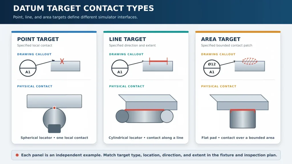
Basic dimensions commonly locate datum targets at theoretically exact positions. That does not mean the tooling, fixture, or measurement process has zero variation. When locator construction tolerance, target-placement tolerance, or measurement strategy can influence acceptance, those requirements should be defined in the applicable drawing, tooling documentation, or agreed inspection plan instead of being improvised after a dispute.
The Target Set, Not One Symbol, Establishes the Reference
A1 alone does not explain how Datum A behaves. The complete target set, its geometry, and its order within the datum reference frame determine which motion is constrained.
The following Contact-to-Constraint Matrix describes a common orthogonal planar 3-2-1 arrangement. It is not a universal recipe for every curved, cylindrical, equalized, movable, or nonrigid target system.
| Datum Order | Common Target Set | Motion Commonly Constrained | Geometry Needed for Stability | Failure Signature When the Set Is Weak |
|---|---|---|---|---|
| Primary A | A1, A2, and A3 as three separated point or area contacts | Translation normal to the primary plane and rotation about two in-plane axes | Three non-collinear contacts forming a stable support triangle | Rocking, tilt, or high sensitivity to one local surface error |
| Secondary B | B1 and B2 after the part is seated on A | One remaining translation and one remaining rotation in a common orthogonal scheme | Adequate spacing and contact that does not lift the part from A | Yaw shift, inconsistent side location, or loss of primary contact |
| Tertiary C | C1 after A and B are established | The final remaining translation in a common orthogonal scheme | Contact compatible with the already established A-B seating | Part shift, forced seating, or overconstraint |
Target spacing controls angular sensitivity. For a simplified rigid-part example, if two locating contacts separated by a span have a relative height difference , the small-angle change is approximately:
If across , then , or about . At a feature 500 mm from the effective rotation origin, that angle can correspond to approximately 0.05 mm of displacement in the affected direction. This is an illustrative geometric calculation, not a machining capability claim; part flexibility, contact form, fixture error, and the complete datum sequence can change the actual result.
This is why targets should not be clustered merely because they are easy to reach. A wide support pattern can reduce angular amplification, but only when the contacts remain on structurally suitable and functionally relevant regions.
More Contact Can Make the Datum Less Repeatable
Datum targets are often introduced to prevent rocking on an imperfect full surface. Adding more rigid contacts without defining how they equalize can recreate the same problem.
Four fixed pads intended to be coplanar may not all contact a rigid part after normal part and fixture variation. On a flexible part, clamp force may pull the fourth location into contact and deform the component into the fixture shape. The part can then measure acceptably while restrained and move after release.
Separate these functions clearly:
- Datum-establishing locators create the reference required by the drawing.
- Supports resist cutting or probing load but should not silently redefine the datum.
- Clamps or hold-downs keep the part seated and can distort it if their force or sequence is uncontrolled.
- Equalized or movable contacts may be appropriate in a designed system, but their behavior must follow the governing drawing and tooling plan.
A datum-target scheme is not permission to force a component into its nominal CAD shape. For sheet metal, thin-wall housings, molded plastics, and other compliant parts, the drawing or inspection plan should state whether evaluation occurs in a free state or under a defined restraint. If restraint is required, locator sequence, support locations, clamp locations, and force limits should be reviewed to the extent that they can change the measured geometry.
The same release-state problem appears in thin-wall aluminum CNC machining: a part can look stable while clamped and change shape after the fixture is opened. Datum targets can make the support condition repeatable, but they cannot remove residual stress or structural compliance.
Put Targets Where the Part Can Carry the Contact
The best-looking flat spot on a CAD model is not automatically a good datum target. Target selection should follow the functional load path, the actual surface condition, and the ability of manufacturing and inspection equipment to reach the same location.
| Tempting Target Location | Why It Looks Convenient | What Can Go Wrong | Better Review Question |
|---|---|---|---|
| Near a trim edge or casting flash | Easy to identify visually | Edge variation, breakout, or flash changes the contact | Will this region remain stable after trimming and deburring? |
| On a thin unsupported panel | Close to the controlled feature | Locator or probe force bends the surface | Is there a stiff load path or a defined support behind the target? |
| Three targets clustered in one corner | Easy fixture and probe access | Small contact span amplifies angular error | Can the stable contact triangle be widened without losing function? |
| Across a weld, parting line, ejector mark, or gate vestige | Existing visible landmark | Local discontinuity creates inconsistent seating | Can the target avoid process-specific surface variation? |
| On a coated or painted patch | Available on the final part | Finish thickness, masking edge, or compression shifts contact | Is datum establishment required before or after finishing? |
| Inside a deep pocket | Protected and close to a critical feature | Fixture and probe access may not reproduce the nominal contact | Can both production and inspection reach it with the correct normal? |
| On a very small rough patch | Minimizes specified area | One asperity or dent dominates the contact | Is the target size compatible with the actual surface and simulator? |
Point targets can also concentrate load. A small-radius spherical-ended locator may create high local contact pressure; on aluminum, magnesium, engineering plastics, coatings, or other relatively compliant surfaces, the applied seating or clamp load can produce permanent indentation and change the effective target height. Locator radius, material pair, surface condition, applied force, support stiffness, expected contact cycles, and allowable marking should be reviewed together. Increasing the locator radius or distributing the load may reduce contact pressure, but it also changes the effective contact patch and its sensitivity to local form; no single locator radius is appropriate for every point target.
Target accessibility must be checked through the whole process, not only on the finished CAD model. A target may be reachable on raw stock but disappear after machining, become covered by finish, conflict with a clamp, or become inaccessible to a CMM stylus. The supplier should also know whether the target surface is as-cast, machined, coated, polished, or otherwise changed before final inspection.
A Fixture and a CMM Can Build Different Datums from the Same Drawing
A physical fixture seats the part against locators under gravity, clamp force, spring force, or another defined load. A CMM may touch discrete points and construct a mathematical alignment. Both methods can be repeatable while producing different references.
| Datum-Establishment Question | Physical Fixture or Gauge | CMM or Digital Inspection | Disagreement Risk |
|---|---|---|---|
| What contacts the part? | Locator tip, pad, pin, rail, or another simulator | Probe points, scan path, or another qualified sensor strategy | Contact geometry is not equivalent |
| Where is contact made? | Actual contact occurs at the locator surface | Software samples commanded locations on the actual part | Probe misses the specified target or samples outside its boundary |
| How is an area target represented? | A bounded pad may contact high regions within the patch | A fitted or constrained construction may use multiple measured points | One center hit is substituted for the entire target area |
| What establishes precedence? | Seating and clamp sequence establish A, then B, then C | Alignment construction order and software constraints establish precedence | Best fit or simultaneous fit overrides datum order |
| What restrains the part? | Gravity, clamps, springs, supports, or fixture nests | Free support, temporary fixture, or programmed restraint assumption | Flexible part changes shape between methods |
| What happens at a burr or local high spot? | It may physically lift the part from a locator | It may be missed, filtered, or treated as an outlier | Physical assembly and digital result diverge |
An unrelated least-squares or global best-fit alignment is not an automatic substitute for the specified target set. Likewise, touching the nominal center of each target does not prove that the CMM reproduced the physical simulator, especially for line and area targets.
For an area target, a fit constrained to remain outside the material may approximate a physical contact pad more closely than an unconstrained least-squares plane in some applications. It is not a universal software setting. The required fitting norm, material-side constraint, void or outlier treatment, sampling pattern, and contact model should be defined by the applicable specification and verification framework together with the agreed inspection plan. ISO 5459 defines the specification operator but does not prescribe one universal physical or mathematical verification operator. Software names and defaults also vary, so the report should identify the actual construction rather than stating only “best fit” or “tangent plane.”
For target-based inspection, the program should define the measured regions, point or scan distribution, probe approach, construction method, datum precedence, and restraint condition. Our CMM inspection guide for CNC machined parts explains why datum alignment, sampling, fitting, and part state must be visible in a useful report.
The Drawing Must Define More Than A1, A2, and A3
Target labels without enough construction information transfer uncertainty to the fixture designer and inspector. A usable drawing and inspection handoff should address the following items.
| Required Item | What It Must Communicate | Risk If It Is Missing |
|---|---|---|
| Governing standard and revision | Whether ASME Y14.5, ISO 5459, or another controlled requirement applies | Symbols and datum-establishment rules may be mixed incorrectly |
| Target IDs and grouping | Which targets belong to Datum A, B, C, or another target set | Individual targets may be combined into the wrong reference |
| Basic target locations | The theoretically exact location of each target from defined references | Fixture and CMM contact different regions |
| Target type and extent | Point, line, or area plus required length, size, shape, or boundary | A different contact form is substituted |
| Surface side and contact direction | Which side is contacted and along which local normal or direction | A mirrored or physically impossible setup is built |
| Datum precedence | How the target-established datums appear in the relevant feature control frame | A simultaneous best fit replaces sequential establishment |
| Part and surface condition | Raw, machined, coated, finished, free, or restrained state | Contact and measured shape change between operations |
| Restraint and support instructions | Required sequence, locations, and force information when they affect shape | Flexible parts are forced into different conditions |
| Controlled characteristics | Which position, profile, orientation, or other requirements reference the datum system | The datum is built correctly but applied to the wrong inspection scope |
| Verification and report scope | Fixture, CMM, gauge, sample quantity, and evidence expected | Supplier and buyer use different acceptance routes |
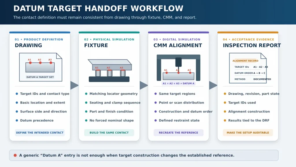
If any of these items is missing, the supplier should clarify them before building dedicated tooling or programming final inspection. A technically exact target location does not, by itself, define every practical detail of the simulator.
Datum Targets Do Not Control the Rest of the Surface
A datum target establishes a reference from designated contact regions. It does not automatically control the form, waviness, profile, surface texture, or clearance of the remaining surface.
This distinction matters on mounting faces, sealing surfaces, cast walls, molded covers, and sheet-metal panels. A part may establish Datum A correctly from A1, A2, and A3 while another portion of the same surface bows into a mating component or violates an assembly envelope.
If the full surface has a functional requirement, specify that requirement separately with the appropriate dimensional or geometric control. Depending on the design, that may involve profile, flatness, orientation, location, surface texture, or a defined assembly envelope. The datum-target callout should not be expected to perform two different jobs.
Use a full datum feature when the complete qualified surface is stable, accessible, and represents how the part actually mates. Use targets when limited contact better represents function or prevents unstable simulation. The choice is a functional decision, not a ranking in which targets are automatically more precise.
A Green Inspection Report Must Still Name the Alignment
A report that says only “Datum A” may hide the most important part of a target-based inspection. The evidence should make it possible to confirm that the required target set and part condition were used.
For critical target-established datums, the agreed report should identify, where relevant:
- Drawing number, revision, units, and governing GD&T standard
- Target sets and IDs used for the alignment
- Point, line, or area representation for each target
- Physical fixture, CMM construction, or gauge method
- Datum precedence and any software alignment constraints
- Free-state or restrained condition and the applied support method
- Finish condition at the time of inspection
- Controlled feature results tied to the correct datum reference frame
- Any approved deviation from the specified simulation method
When the target-based alignment is part of a formal first-off approval, the ballooned drawing and report scope should connect the target IDs to the measured characteristics. Our guide to first article inspection explains why the approval scope must be defined rather than inferred from a generic PASS result.
Two inspection methods do not have to use identical hardware. They do need to establish an equivalent datum under the governing drawing and agreed verification plan. If equivalence cannot be demonstrated, the buyer and supplier should resolve the method before using one result to reject the other.
Quote the Contact Scheme, Not Just the Geometric Tolerance
Before quotation, send the 2D drawing and 3D model together with the governing drawing standard, target IDs, target types and sizes, basic locations, datum precedence, part state, finishing condition, controlled characteristics, and required inspection evidence. For flexible parts, include the intended support and restraint condition. If the target scheme represents an assembly fixture or mating component, provide that interface information when available.
Rapid Efficient can review datum-target accessibility, machining-reference transfer, workholding contact, surface-condition risks, CMM alignment requirements, and requested reporting scope before quotation. The final interpretation remains tied to the customer drawing and the agreed inspection plan.
For suitable projects requiring controlled datum relationships and inspection planning, review our precision machining services.