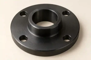
A machined mounting face can pass a flatness check and still put the mating part at the wrong angle. The missing requirement may be the face’s orientation to the mounting datum.
Flatness controls the form of a surface without a datum reference. Surface parallelism controls that surface within a tolerance zone oriented to a specified datum. A face can therefore be flat and still fail parallelism.
The examples below concern individual planar surfaces. Axis controls and controls applied to a derived median plane need separate interpretation under the drawing’s specified GD&T standard.
A Perfectly Flat Face Can Still Fail Parallelism
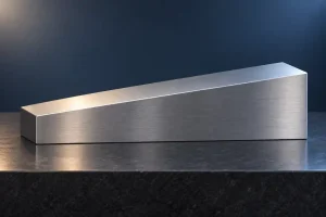
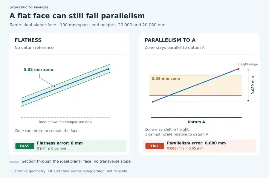
Consider an ideal, rigid block with a perfectly planar bottom face establishing datum A. Its upper face is also perfectly planar, but it slopes along a 100 mm length.
Measured perpendicular to datum A, the upper face is 20.000 mm high at one end and 20.080 mm high at the other. There is no additional slope across the width.
Suppose the drawing requires upper-face flatness of 0.02 mm and parallelism of 0.05 mm to A.
| Characteristic | Geometric result in this example | Drawing limit | Result |
|---|---|---|---|
| Upper-face flatness | 0 mm: the ideal surface has no form error | 0.02 mm | Pass |
| Upper-face parallelism to A | 20.080 − 20.000 = 0.080 mm | 0.05 mm | Fail |
For flatness, the enclosing planes can follow the upper face’s slope. For parallelism, they must remain parallel to datum A.
These are idealized geometry values, not measured production results or recommended machining tolerances.
The correction must change the upper face’s orientation to datum A.
Read the Two-Plane Zone Before Adding a Callout
A surface-flatness tolerance of 0.02 mm requires the controlled surface to fit between two parallel planes 0.02 mm apart. Their orientation is not tied to another feature. The value is the total zone width, not ±0.02 mm.
A surface-parallelism tolerance of 0.05 mm to A also uses two parallel planes. This time, their orientation is fixed parallel to datum A. The tolerance is a distance, not an angle in degrees.
KEYENCE’s guides to form tolerances and orientation tolerances illustrate these different zone constraints.
The face marked A is the real datum feature. Datum A is the ideal reference established from that feature under the applicable drawing rules. The real face can have form error; adding the letter A does not make it perfectly flat.
Keep these roles separate when reviewing a drawing. Identify the controlled face, the datum feature used for orientation, and any independent requirement on the datum feature itself.
When Both Controls Belong on the Same Face
Surface parallelism also limits surface form. If the entire controlled face fits inside two planes 0.05 mm apart and parallel to A, it necessarily fits inside a two-plane flatness zone no wider than 0.05 mm.
That geometric relationship explains when a separate flatness callout adds value.
Suppose a mounting face needs parallelism of 0.05 mm to the base, but its contact function requires flatness of 0.02 mm. Both controls can serve a purpose:
- The 0.05 mm parallelism zone limits the combined effect of surface form and orientation relative to A.
- The 0.02 mm flatness zone imposes a tighter form limit on the face itself.
A face with 0.03 mm of flatness deviation could fit inside the 0.05 mm parallelism zone and still fail the separate 0.02 mm flatness requirement.
These limits are not added together. Each requirement must be satisfied.
For the same surface extent and part condition, adding flatness of 0.05 mm to parallelism of 0.05 mm provides no tighter form limit. Check the functional need before adding another callout and inspection item.
The comparison changes if the controls apply to different areas. A local requirement over a limited length is not the same as whole-face flatness. Our flatness per unit length guide explains that distinction.
Keep Datum A in the Inspection
A surface plate and indicator can support a parallelism check on a suitable rigid part when the setup correctly establishes the specified datum. Clean the contact surfaces, check seating, and sweep enough of the controlled face to assess variation across its area.
The height range is then an estimate of parallelism relative to that reference. Rocking, burrs, inadequate coverage, or deformation under contact force can change the result.
For flatness, the evaluation must allow the enclosing planes to find their orientation independently of the opposite face. A raw indicator range from an arbitrarily tilted setup is not automatically a flatness result. Leveling three selected points alone also does not establish the minimum enclosing zone for the whole measured surface.
If the drawing establishes A through specific contact locations, reproduce that contact scheme. The datum targets guide explains why selected support areas can differ from using the entire face.
Do not replace a datum established from the complete face with three convenient support points simply to stop rocking. An alternative contact scheme must be reviewed against the drawing’s datum requirements.
A CMM must retain both orientation and surface form
Establish datum A using the specified datum feature and an appropriate evaluation method. Evaluate the controlled surface relative to that reference.
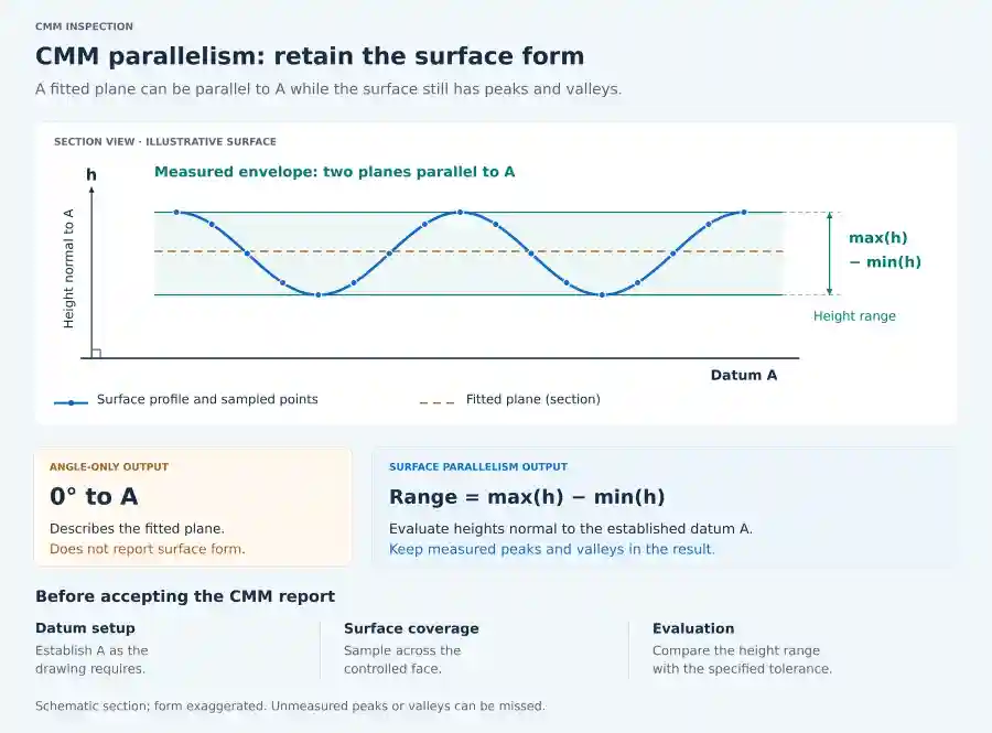
Comparing only the angle between two fitted planes is insufficient for surface parallelism. It describes their relative orientation but can leave surface peaks and valleys out of the result. Conversely, leveling the upper face and reporting only its residual form can remove the tilt that the parallelism control was intended to limit.
Mitutoyo’s CMM measurement planning guidance specifically illustrates the error of evaluating parallelism without including surface form.
| Measurement output | What it can establish | What it does not establish by itself |
|---|---|---|
| Flatness evaluated from a surface point set | Form of the sampled surface under the stated evaluation method | Orientation to datum A |
| Maximum minus minimum surface height measured normal to an established datum plane A | Parallelism deviation of the sampled surface to A | Adequate coverage of unmeasured areas |
| Angle between fitted upper and datum planes | Relative orientation of those fitted planes | Full surface-parallelism deviation, including form |
| Micrometer thickness readings at selected locations | Local two-point thickness | Complete surface form or the required datum relationship |
The measurement strategy matters as much as the reported characteristic name. NPL’s CMM measurement strategies guide explains how point distribution and expected surface form affect the result. Sparse points can miss bowing or waviness between sampled locations.
Choose coverage for the surface and tolerance being checked. A program’s minimum point count for constructing a plane is not evidence that the whole face has been adequately inspected.
For report review, identify the datum construction, surface extent, sampling strategy, evaluation method, and support condition. Our CMM inspection guide covers the wider report requirements.
Specify the Height and Support Condition as Well
Parallelism does not set the distance between the controlled face and datum A. Moving a planar face farther from A without changing its orientation can leave both flatness and parallelism unchanged while making the part too thick or too tall.
Define the required thickness or location separately, and read it together with the geometric controls and the drawing’s stated standard and edition.
For a rail mounting face, for example, review three different questions: how much surface form error the contact can accept, how much tilt is acceptable relative to the mounting base, and where the face must sit in the assembly. One flatness value cannot answer all three.
Support conditions also need agreement on flexible parts. Clamping a thin plate down can change the geometry being inspected. If acceptance is under a restrained condition, define the supports and restraint; if it is in a free state, use a setup consistent with that requirement. Do not increase clamping force simply to obtain a passing reading.
For a machined base, rail mount, or spacer, share the drawing with the working face, datum feature, height or thickness requirement, and inspection support condition clearly identified. If two reports disagree, include their alignment methods and measured surface data.
Through our CNC machining services, Rapid Efficient can review how these requirements affect machining setups and inspection planning before quotation. The aim is to agree on how the specified datum will be established, how the part will be supported, and how the finished face will be accepted.