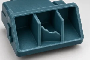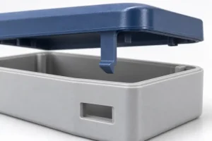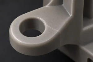

Knit lines in injection molding form where separated melt fronts meet and join. Also called weld lines, these regions may show a fine line, notch, or change in gloss. Their mechanical behavior can differ from the surrounding material, but a visible line alone does not show whether the part meets its requirements.
The useful distinction is between improving the mark and proving the molded feature. A less visible line may satisfy an appearance requirement while leaving a question about impact, repeated loading, or cracking during assembly. Identify the joining region, relate it to the part’s load, and choose an acceptance test before treating a cosmetic improvement as a complete correction.
Read the Line Against the Filling Pattern
A single gate can produce a knit line. Melt can divide around the core that forms a hole and meet again downstream. Multiple gates provide another route for separate fronts to meet. Changes in wall thickness can also alter the filling sequence and meeting location.
These joining regions are different from a parting-line witness mark left by the interface between mold components. Flow marks, scratches, and ejection damage can also resemble lines without having the same cause. Compare the mark with the gate locations, openings, mold interfaces, and direction of release before choosing a remedy.
Keep an unaltered sample and record the cavity number. A line visible in one photograph but not another may reflect lighting rather than a process change. Inspect the same region under consistent conditions, including the opposite face where accessible.
Molding software may distinguish weld lines from meld lines according to how the fronts meet. Those labels help describe filling behavior; they are not acceptance grades. Autodesk’s weld- and meld-line guidance explains the distinction and notes that a coarse simulation mesh can miss lines.
A controlled short-shot sequence can help reveal where the fronts separate and approach each other. Record the trial conditions, because an incomplete fill does not reproduce every condition in the final packed part. Use it to investigate the flow path, then confirm the joining region on complete molded samples.
Follow the Load Through a Molded Mounting Ear
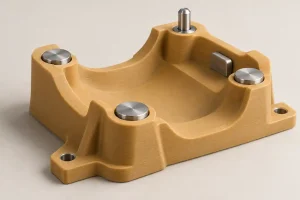
Consider a plastic bracket with a mounting ear and a hole formed by a core pin. This is an illustrative design example, not a reported customer project. Suppose the proposed filling pattern places a joining region between the hole and the ear’s outer edge.
The hole may pass dimensional inspection, and the bracket may accept its fastener. Neither result establishes how the ear behaves when the assembly pulls or bends it. Fastener contact, support conditions, and the remaining material around the hole determine the local loading.
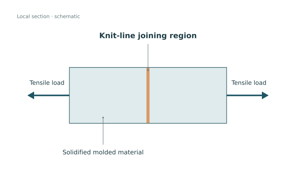
Tension acting across a joining region tends to open it. However, a surface line is only a trace of a three-dimensional region. Its visible direction alone cannot establish the complete stress state or prove that another load direction is harmless. Review the actual assembly rather than assigning strength from a photograph.
Assess the joining region against the load it must carry, including the way the fastener and surrounding parts support it.
Moving the gate may move the joining region away from a loaded section. The new location still needs review: it might place the meeting region near another mounting feature or change filling elsewhere. The injection molding gate guide covers gate placement, separation, and residual marks; the additional question here is whether the resulting joint is acceptable under load.
Material selection does not remove that question. In a glass-filled resin, local fiber orientation can provide less reinforcement across the joining region than a bulk material property suggests. Do not apply the tensile strength from a material datasheet directly to that region without examining how the value was obtained and whether it represents the molded feature.
Similarly, replacing an unfilled resin with a reinforced grade changes more than a strength number. Review the new grade’s filling behavior, orientation, dimensions, and performance on molded samples before approving the substitution.
Choose a Correction That Addresses the Joining Conditions
Before a trial, state what you want to change: line visibility, cracking during assembly, load capacity, or another defined result. Then identify a plausible cause and a response that can test it. Changing several settings without preserving a baseline makes the result difficult to interpret.
Temperature and filling speed. Review the actual melt and mold conditions against the resin supplier’s processing guidance. Warmer meeting fronts may join more effectively, but temperature increases must remain within the material’s limits. A faster fill can shorten the time available for the melt fronts to cool before they meet. However, it can worsen problems caused by trapped air.
BASF’s injection-molding troubleshooting guide makes that distinction in its weld-line section: increasing injection speed may help, while venting problems can call for a reduction. It also identifies vent cleaning and mold-related changes as separate corrective routes.
Air escape. Check whether air can leave the area where the fronts meet. An existing vent may be obstructed or poorly placed for the actual filling pattern. Clean and assess it before assuming the process needs more pressure. Any vent modification should suit the resin and tool; an oversized escape path can create flash.
Pressure and transfer. Check whether the intended filling and packing sequence is being achieved. Raising holding pressure alone does not establish that a poorly joined region has recovered. Excess pressure may create another defect, covered in the injection molding flash guide.
Flow-path changes. Gate relocation or a wall-section change can alter where and how the fronts meet. Adding a gate may shorten a flow path while introducing another meeting region. Evaluate the revised filling pattern before machining the tool, and identify which dimensional and functional approvals the change affects.
Polishing the cavity, changing texture, or applying a coating may alter visibility. These actions do not, by themselves, demonstrate stronger joining through the section. If the problem is mechanical, the trial must include a mechanical response.
Record appearance and functional results separately for each trial condition. Retain identified samples and note material preparation, cavity, process settings, and the changed variable. Once a promising condition is found, confirm that it works across the production conditions the project intends to approve.
Test the Property the Part Actually Needs
“Weld-line strength” needs a test definition. Tensile strength, elongation at break, impact response, repeated-load life, and resistance to sustained loading describe different behavior. A result for one does not establish the others.
Covestro’s technical discussion of weld-line performance compares single- and double-gated polycarbonate tensile specimens. In the reported example, yield behavior remained similar while elongation at break fell substantially. That is a useful reason to examine the failure mode rather than approve a part from one strength value. The result belongs to the tested material and specimens; it is not a universal reduction factor.
A practical acceptance plan can connect the joining region to the function at risk:
| Joining region on the part | Load or function to reproduce | Evidence to record beyond line visibility |
|---|---|---|
| Between a mounting hole and the edge of an ear | Fastener contact and the specified pull or bending load | Load and displacement, crack origin, failure location, and any permanent deformation |
| Across a screw boss | The specified fastener, assembly method, and relevant service loading | Cracking during assembly and performance after assembly; installation torque alone is not a complete strength test |
| Through a wall that contains pressure or fluid | The required pressure, temperature, duration, and fluid conditions | Leakage or pressure-test results under the agreed conditions; a visible line does not automatically mean a leak |
| Across a repeatedly flexed feature | The intended deflection, direction, and number of operations | Crack development and loss of retention or function during the test |
| On a cosmetic face with no identified local load requirement | The specified viewing conditions and finished surface state | Appearance limits and approved boundary samples; this approval does not cover untested mechanical behavior |
Set the numerical limits and sampling plan from the product requirements. The table identifies useful evidence; it does not prescribe a universal test load, cycle count, or acceptable crack size.
Test the molded feature with the support and loading conditions that matter in the assembly.
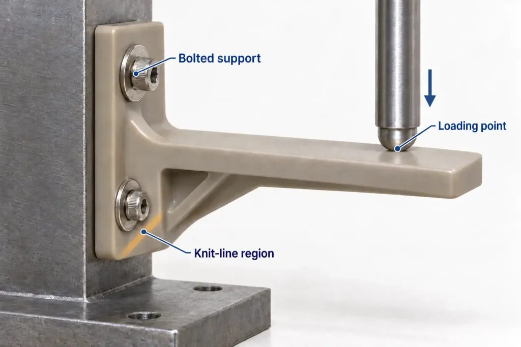
A tensile specimen can help compare material behavior, but it does not reproduce every feature of the bracket. A bracket test that breaks elsewhere establishes the load reached before that failure; inspect the joining region separately for damage. It does not establish that region’s ultimate strength or long-term life.
Use the intended resin grade, reinforcement, color package, and relevant conditioning. For moisture-sensitive materials, specify the condition at testing. A dry laboratory sample and a conditioned production part should not be treated as interchangeable without review.
Define appearance acceptance separately, using the viewing setup and finish boundaries described in the injection molding surface finish guide. If painting follows molding, identify whether approval covers the as-molded surface, the painted surface, or both. A coating that hides the line supplies no direct evidence of the strength beneath it.
Keep the approved part revision, resin specification, cavity identity, trial condition, and test results together. For a multicavity tool, define which cavities the evidence covers. A change in gate layout, material, or process should trigger a review of the affected approvals rather than automatic acceptance based on the earlier sample.
For a part with a knit line near a loaded feature, share the model, marked line location or sample photographs, exact resin grade, and the assembly’s load or failure requirement. Rapid Efficient can review the molding route and coordinate the agreed sampling and inspection scope through its injection molding services. Specify any required functional testing before quotation so its method, responsibility, and deliverable are clear.