RapidEfficient manufactured an aluminum housing for a laser cutting head assembly. Although the component looked like a compact machined enclosure, it connected mechanical mounting, optical-component location, the nozzle interface, internal cooling and gas passages, threaded ports, and anodized surfaces.
The manufacturing challenge was not one isolated “high-precision” dimension. It was maintaining the relationship among these functions after heavy material removal, unclamping, multi-side machining, cleaning, and surface treatment.
A bore could meet its size limit but still be incorrectly located relative to the mounting face. An internal passage could be open but contain a breakthrough burr. A thin wall could measure correctly while clamped and move after release.
Quick Answer
Laser cutting head housing machining requires coordinated control of the mounting datums, optical-component bore, nozzle interface, internal cooling and gas passages, thin-wall geometry, threaded ports, and post-anodize dimensions. RapidEfficient managed these risks through staged material removal, low-distortion workholding, controlled datum transfer, multi-side machining, passage cleaning, and feature-specific inspection. Final optical alignment and cutting performance remained assembly-level acceptance requirements.
Project Overview
| Project Item | Project Requirement |
|---|---|
| Component | CNC-machined laser cutting head housing |
| Material | Aluminum alloy |
| Application | Laser cutting head assembly |
| Main geometry | Thin walls, stepped internal bores, multi-side ports and internal passages |
| Functional interfaces | Mounting face, optical-component bore, nozzle interface and threaded connections |
| Internal features | Cooling and gas passages |
| Surface treatment | Anodizing per project drawing |
| Main manufacturing risks | Distortion, datum transfer, passage breakthrough burrs, sealing-interface damage and coating interference |
| Inspection approach | Feature-specific dimensional inspection referenced to the drawing datums |
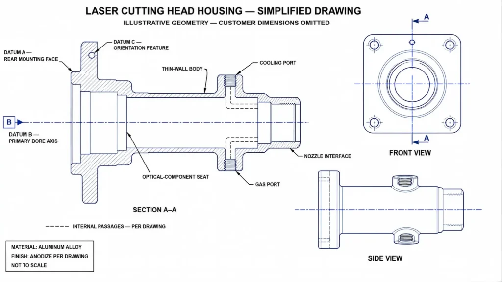
To protect customer confidentiality, identifying information and selected drawing dimensions are not disclosed.
Why This Housing Could Not Be Treated as a General Aluminum Enclosure
A laser cutting head housing participates in several functional systems at the same time.
It supports components associated with the beam path, connects to the nozzle assembly, routes cooling media and cutting gas, provides mounting interfaces, and protects internal components from contamination and handling damage.
However, the housing alone does not determine beam quality or final cutting performance. Mechanical machining can control the physical features that support alignment, but it cannot directly certify the optical axis of a fully assembled cutting head.
The project therefore required the system requirements to be translated into machinable and inspectable features.
| Functional Requirement | Machinable Feature | Main Manufacturing Risk | Suitable Evidence |
|---|---|---|---|
| Optical-component location | Stepped bore or locating seat | Bore size is correct but its axis shifts relative to the mounting datums | Bore size, form and datum-related position |
| Nozzle alignment | Locating or threaded nozzle interface | Setup transfer creates angular or radial mismatch | Interface axis and face relationship |
| Cooling route | Internal passages and threaded ports | Breakthrough burrs, blockage, insufficient remaining wall or leakage | Passage inspection and specified functional test |
| Gas delivery | Internal gas path and nozzle connection | Restriction, contamination or damaged sealing features | Cleanliness and test requirements defined by the drawing |
| Machine installation | Mounting face and hole pattern | Thin-wall movement changes the installed relationship | Flatness, position and orientation from agreed datums |
| Surface protection | Anodized surfaces | Coating changes fit, threads or contact interfaces | Post-finish dimensional and visual inspection |
This function-to-feature map was more useful than applying one general precision note across the entire housing.
We Converted the Assembly Relationship into Physical Datums
The optical axis is an assembly-level function. A CMM can inspect the housing’s mechanical features, but it cannot establish the operating beam path of the assembled optical system.
The drawing therefore needed physical reference features that could be established during machining and reproduced during inspection.
For the simplified figures on this page:
- Datum A represents the primary mounting face.
- Datum B represents the primary functional bore axis.
- Datum C represents an orientation feature used to control angular position.
The customer drawing governed the actual acceptance requirements.
The mounting face established how the housing located in the larger assembly. The primary bore established the mechanical axis for the internal component stack. The orientation feature controlled the relationship of side ports, mounting holes, and internal passages around that axis.
The seating face for an optical component also had to be controlled relative to the primary bore axis. Where practical, the seat and bore were finished from the same stable reference so that bore size, seat orientation, and interface location did not accumulate through unrelated setups.
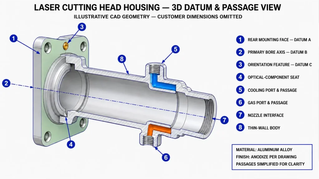
The machinable reference system therefore had to convert an assembly axis into physical datums that could be established again during machining and inspection.
Where access allowed, related bores, faces, and interfaces were finished without unnecessarily breaking their datum relationship. Features that required another setup were re-established from stable machined references rather than unfinished stock surfaces.
Internal Cooling and Gas Passages Required More Than Drilling
A drilled passage is not automatically a finished functional channel.
Intersecting holes can leave burrs at the point of breakthrough. Long or angled passages can trap chips. Threaded ports may contain damaged lead threads or residue after cleaning. A passage can also break too close to an external wall, sealing face, or adjacent cavity when the drawing does not clearly define its route.
At cross-drilled intersections, residual burrs or loose chips could restrict the intended passage, disturb gas delivery, or contaminate adjacent components. The deburring and cleaning method therefore had to match the passage geometry and available inspection access.
The DFM review considered:
- Entry and exit access for each passage
- Intersections between drilled channels
- Remaining wall around the passage
- Thread engagement and port sealing
- Access for deburring and flushing
- Plug or closure requirements
- Features requiring protection during anodizing
- Required passage inspection or functional testing
Cooling and gas passages also required different acceptance logic.
A dimensional inspection can confirm a port location, diameter, or thread. It cannot by itself prove cleanliness, unrestricted flow, or leak performance. When a functional flow, pressure, or leakage requirement applies, the drawing or purchase specification must define the test medium, pressure, duration, allowable leakage, and acceptance condition.
The Machining Route Preserved the Functional Relationships
The process was divided into controlled stages rather than attempting to complete every feature immediately after the first setup.
1. Review the Drawing as a Functional System
The initial review separated:
- Mounting datums
- Optical-component locating features
- Nozzle-related interfaces
- Cooling and gas passages
- Threaded connections
- Thin-wall regions
- Sealing surfaces
- Anodizing boundaries
- Inspection requirements
This prevented a visually prominent surface from receiving more attention than a less visible but functionally critical interface.
2. Establish Stable Reference Features
Initial machining created repeatable locating surfaces without removing all surrounding support.
The objective was to produce references that could survive the later roughing, release, and re-clamping stages.
3. Remove the Main Material in Controlled Stages
Major cavities and external reliefs were roughed before final alignment features were completed.
Material removal was distributed to reduce abrupt stiffness changes. Cutting engagement, tool projection, and chip evacuation were controlled around thin walls and deep internal areas.
For a deeper explanation of released-part movement, see the thin-wall aluminum CNC machining guide.
4. Release the Part and Re-Establish the Datums
Unclamping does not remove residual stress, but it exposes movement that the fixture may have been hiding.
After the main stock removal, the housing was returned to a stable reference condition before the final machining of alignment-critical features.
The process route preserved rigid locating regions until the alignment-critical features could be finished from a controlled reference state.
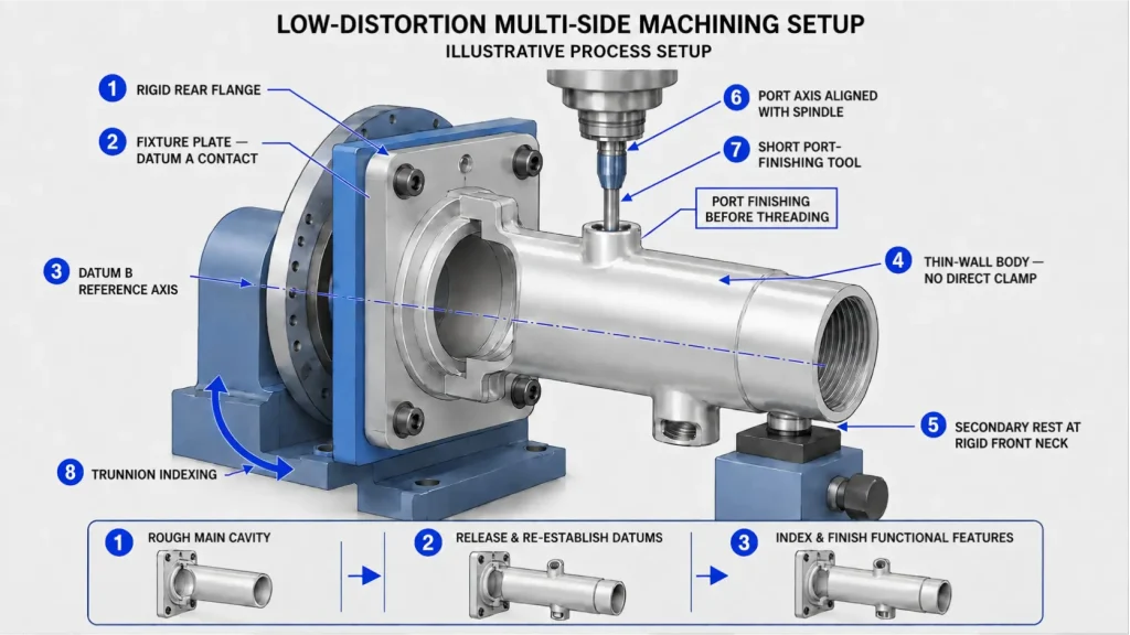
5. Coordinate Multi-Side Features
Selected ports, bores, and faces required access from different directions.
Multi-axis positioning reduced unnecessary setup transfer for suitable features, but it did not mean that every surface had to be machined simultaneously or in one universal setup. The process choice depended on tool access, feature relationships, part stiffness, and inspection strategy.
The distinction between genuine five-axis need and avoidable process complexity is explained in the 5-axis vs 3-axis CNC machining guide.
6. Finish Passages, Threads, and Sealing Interfaces
The final sequence protected features that could be damaged by later cutting, deburring, or handling.
Passage intersections were checked and cleaned. Thread starts and sealing interfaces were kept free from raised burrs. The housing was cleaned before surface treatment so that chips or residue were not carried into the finishing stage.
Low-Distortion Workholding Supported Rigid Regions
The fixture located the housing from stable features and distributed holding force through comparatively rigid regions.
Unsupported thin walls were not used as the primary clamping surfaces. Clamp force was limited to what was required to resist the cutting load, and the tightening sequence remained repeatable.
This mattered because a flexible housing can appear correct while the fixture is forcing it into shape. After release, the same wall or mounting flange can move and change the relationship among the functional features.
Final dimensional verification therefore used the agreed released or restrained condition rather than an informal inspection setup.
Anodizing Was Included in the Tolerance Chain
Anodizing was not treated as a cosmetic operation added after machining was complete.
The finish could affect:
- Locating bores
- Threaded ports
- Sealing surfaces
- Component seats
- Edge condition
- Surface appearance
There is no universal coating allowance that can be applied to every bore, thread, or mating surface. The required response depends on the anodizing specification, coating thickness, material, fit, masking plan, and whether the drawing dimensions apply before or after finishing.
For coolant sealing interfaces, the drawing needed to define the seal geometry, required surface condition, anodizing or masking boundary, cleanliness requirement, and final test condition. A universal roughness value or coating rule could not be applied without the mating-seal design.
The project drawing therefore controlled which areas received the finish and which dimensions required post-finish verification.
For related finish-planning considerations, see the aluminum anodizing and powder coating guide.
Inspection Had to Match Each Functional Feature
Critical dimensional relationships were evaluated from the drawing datums. CMM inspection supported features involving position, orientation, and multi-feature relationships, but it was not treated as a universal answer for every requirement.
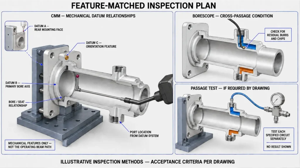
Inspection therefore matched each characteristic to a method capable of evaluating that feature in the agreed part state.
| Feature | Suitable Inspection Approach | Main Control Point |
|---|---|---|
| Primary mounting face | CMM or defined surface-plate method | Support condition and datum establishment |
| Functional bore size | Bore gauge, air gauge or suitable CMM strategy | Contact force, depth and temperature |
| Bore axis relative to mounting datums | Datum-aligned CMM measurement | Alignment method and feature construction |
| Side-port position | CMM or functional fixture | Relationship to Datum B and Datum C |
| Internal threads | Suitable thread gauges and visual inspection | Thread class, lead condition and finish state |
| Sealing interfaces | Dimensional and visual inspection | Burrs, dents, coating and contact condition |
| Internal passages | Visual, borescope, flow or pressure/leak method when specified | Accessibility and documented acceptance criteria |
| Post-anodize fits | Appropriate dimensional gauge | Final coating and temperature condition |
For repeat production, any required first article package should identify which dimensions are inspected before finishing and which control the final anodized condition. The first article inspection guide explains why ballooned drawings, method agreement, and result traceability must be coordinated before repeat production.
Project Outcome
The laser cutting head housings were manufactured through a controlled sequence covering datum establishment, staged material removal, multi-side machining, passage deburring and cleaning, anodizing preparation, and final inspection.
The completed housings were supplied for customer assembly after inspection against the project drawing and agreed acceptance requirements.
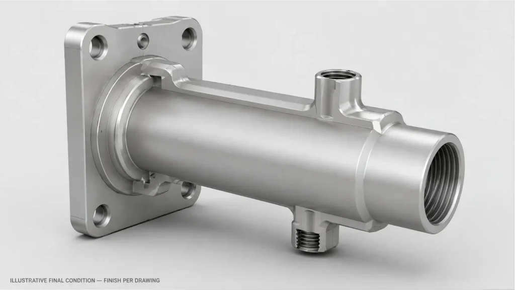
Housing inspection established the required mechanical interfaces. Final optical alignment, focus behavior, cooling performance, gas delivery, and cutting quality remained part of the assembled cutting-head system rather than claims inferred from the machined housing alone.
The project demonstrated that reliable laser cutting head housing machining depends less on one impressive tolerance and more on keeping the datum structure, internal passages, thin-wall behavior, surface treatment, and inspection plan connected.
What Buyers Should Define Before Requesting a Quote
A useful laser cutting head housing review should include:
- 3D CAD model
- Complete 2D drawing
- Aluminum alloy and temper
- Required quantity
- Mounting datum structure
- Optical-component and nozzle-related interfaces
- Critical bore size, form, position, and orientation requirements
- Internal cooling and gas-passage drawing
- Thread and sealing requirements
- Plug or passage-closure details
- Flow, pressure, or leakage test requirements
- Anodizing specification and masking boundaries
- Pre-finish and post-finish dimensional requirements
- Cleanliness and flushing requirements
- First article and production inspection documentation
RapidEfficient can review the machining sequence, workholding, datum transfer, passage access, anodizing boundaries, and inspection plan through our precision machining support.
To evaluate the project, send the drawing package and functional requirements together with the required quantity and acceptance documentation.