加工颤振: 查找原因并测试修复方法

铣削可以沿着直壁平滑地进行, 然后在内角留下波浪. Another cut may become unstable only after the surrounding stock has been removed. Both problems can be called machining chatter, but they need different checks.

Machining chatter is a self-excited vibration that develops through the interaction between cutting forces and movement of the tool and workpiece. It can damage the surface, change dimensions, and shorten tool life. 然而, a noisy cut or a repeating tool mark does not prove that chatter is the cause.

Start by recording where the cut changes. Check the tool and support, then make a controlled adjustment and compare the result. The examples below focus on milling; turning and boring need different feed and cutting-contact assumptions.


Find Where the Chatter Starts

Before changing the program, identify the first affected location and the operation that produced it. Record whether the problem starts at entry, inside a corner, deep in a pocket, or after a wall becomes thinner.

Also compare the affected cut with a nearby stable cut. Differences in reach, remaining stock, 订婚, or support can help narrow the investigation.

Before testing new cutting settings, check for a damaged cutting edge, poor tool seating, or loose workholding. Then use the location and timing of the marks to choose the next check.

Observed changeFirst area to checkA useful comparisonLimit of the conclusion
Straight cut is acceptable; an inside corner develops wavesLocal cutter engagement and stock left in the cornerCompare a revised corner path with similar incoming stockImprovement identifies a sensitive cutting condition, not the vibration mechanism by itself
The problem starts after changing to a longer tool assembly工具投影, holder connections, and assembly stiffnessTest a shorter assembly where access allows, with cutting data suited to that assemblyA different tool may also change edge condition and geometry
The same path becomes unstable as a wall gets thinnerWorkpiece stiffness, 支持, 和加工顺序Compare cuts at a similar wall thickness with revised supportEarly roughing and final finishing are not equivalent tests
A previously stable process becomes worse over several partsEdge wear, built-up material, 排屑, and seatingInspect and restore the affected condition, then repeat a comparable cutReplacing several items together does not identify which one mattered
Reducing feed makes the surface worseActual chip thickness, 边缘条件, and rubbingReview feed against the tool supplier’s guidance and actual engagementThe result does not justify increasing feed without checking the other limits

Use these patterns to choose the next check, not to label the cause from appearance alone.

Take a close photograph and mark the location on the drawing or toolpath. On a face-milled surface, ordinary feed marks, one dominant insert track, and overlapping passes can resemble a vibration problem. 这 face milling guide explains these surface-pattern differences.


Separate Chatter from Other Cutting Problems

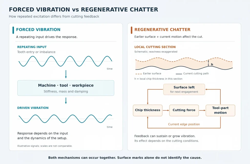
Forced vibration is a response to a repeating input, such as tooth entry, 不平衡, or unequal cutting loads. Its size depends on both the input and the dynamic response of the machine, 工具, 和工件.

Regenerative chatter involves feedback through the surface left by earlier cutting. A vibrating edge leaves a wave. The next edge cuts a chip whose thickness depends on that wave and its own current position. The resulting force can sustain or increase the vibration.

The distinction is between a driven response and an unstable cutting feedback process. The review by Altintas and coauthors explains these machining dynamics and the regenerative mechanism. Chatter Stability of Machining Operations

The two mechanisms can occur together, so surface marks alone do not identify which one is present.

Forced vibration and regenerative chatter comparison showing periodic input and feedback through surface waviness, 切屑厚度, 切削力, and tool motion

Other problems can complicate the picture. Runout can make one tooth carry more load. A worn edge may rub, while built-up edge or trapped chips can tear or scratch the surface. These conditions can worsen vibration, but each also needs its own correction. For aluminum-specific examples, 看 aluminum machining problems.

If frequency measurements are available, compare them with spindle rotation, tooth-passing frequency, and the machine’s measured response. Treat this as supporting evidence. A phone recording is useful for documenting a change, but it is not a calibrated displacement measurement or a part-acceptance result.


Check the Tool and the Part for Movement

There are two sides to the cutting contact: the tool assembly and the supported workpiece. Improving one side may have little effect if the other side still moves easily under the cutting force.

With the machine stopped, inspect the cutting edges, tool seating, holder interfaces, and fixture contacts. Check tool runout using a method and limits appropriate to that assembly. If there is evidence of poor tool retention or spindle damage, follow the machine builder’s inspection procedure before continuing cutting trials. Haas includes tool wear, excessive reach, and drawbar holding force among its milling troubleshooting checks. 哈斯: Mill Chatter Troubleshooting

For a deep feature, review the whole tool assembly. A short flute length does not cancel the effect of a long neck or extended holder. Use the shortest practical reach while keeping the required access, grip length, and holder clearance.

On the workpiece side, place support where it can resist the actual cutting-force direction. Increasing clamp force is a different action: it may distort a thin wall without supporting the region being cut.

Support also changes as material disappears. A setup that works during roughing may not remain suitable for the final wall pass. 这 薄壁铝CNC加工指南 covers this changing geometry and the importance of checking the part after release.


Test Spindle Speed While Tracking Chip Load

Lower spindle speed is not automatically more stable. A particular tool and setup can have stable and unstable combinations of speed and cutting depth. Changing speed in either direction may improve the cut within the tool and machine’s operating limits.

同样地, lowering feed can make an already thin chip too small for effective cutting. Sandvik notes that rubbing can occur at low chip thickness and that increasing feed per tooth may help in that condition. Its guidance also describes how a speed increase can move a cut into a more stable region. Sandvik Coromant: Milling Vibration

Separate a speed test from a chip-load change

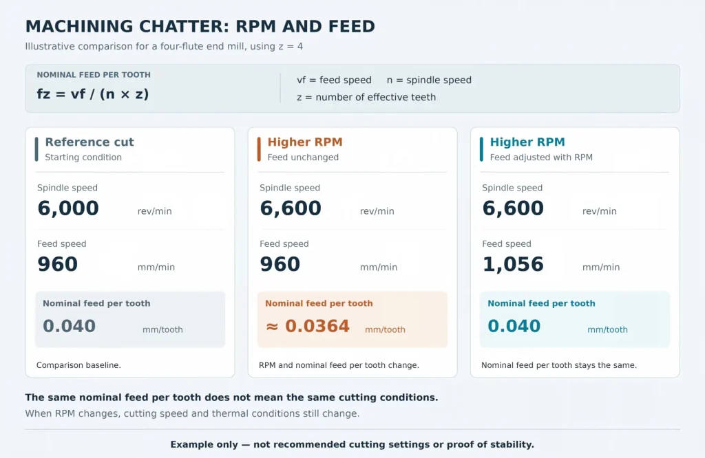
For a cutter with a known number of effective teeth, nominal feed per tooth follows:

vf = n × z × fz

这里, vf is feed speed in mm/min, n is spindle speed in rev/min, z is the number of effective teeth, 和 fz is feed per tooth in mm/tooth.

At a fixed feed speed and tooth count, lowering RPM increases nominal feed per tooth; raising RPM decreases it.

Consider an illustrative four-flute end mill, using z = 4:

Test condition主轴转速进给速度Nominal feed per tooth
Reference6,000 rev/min960 毫米/分钟0.040 毫米/齿
Higher RPM; feed unchanged6,600 rev/min960 毫米/分钟关于 0.0364 毫米/齿
Higher RPM; feed adjusted6,600 rev/min1,056 毫米/分钟0.040 毫米/齿

These numbers show the feed relationship only; they are not recommended cutting settings.

Milling speed test comparison showing how changing RPM with fixed or adjusted feed affects nominal feed per tooth

In the second row, both speed and nominal chip load change. In the third, feed is scaled with RPM to preserve nominal feed per tooth. That makes the comparison easier to interpret, but cutting speed and thermal conditions still change.

Nominal feed per tooth is not the actual chip thickness at every point. At low radial engagement, the maximum chip thickness can be lower than nominal feed per tooth. Check the tool supplier’s guidance for the actual cutter geometry and engagement before adjusting feed. 这 cutting speed for aluminum milling guide explains the related cutting-speed and feed terms.

Keep the comparison meaningful

Use a comparable cut length, 库存津贴, 订婚, 工具状况, 和支持状态. Record the actual speed and feed, including overrides. Check how the control handles any spindle-speed change rather than assuming feed will follow automatically.

A second pass over the same surface is not an equivalent test if the first pass removed most of the stock. Its quieter sound may come from lower engagement. Use a comparable feature, test piece, or planned allowance when evaluating the change.

If a bounded speed trial does not help, revisit the engagement, tool assembly, or workpiece support. Do not keep searching for a universal RPM that can compensate for a loose or unsuitable setup.


Control Engagement at Corners and Entries

A constant programmed feed does not mean a constant cutting load. As a cutter enters an inside corner, more of its circumference may contact the material. Uneven stock left by roughing can add another local load increase.

Review the simulated engagement and the stock actually entering the operation. 取决于功能, useful changes may include removing corner stock earlier, using a smaller cutter with a more gradual path, reducing local engagement, or changing the entry move. Haas identifies corner geometry and toolpath-related load increases as specific troubleshooting areas in its milling guide.

A smaller cutter also has different stiffness and cutting-speed requirements. Check those effects when comparing the revised path; changing diameter alone does not establish a better process.

Choose entry and exit moves for the actual tool, 材料, and available space. Ramping can provide a smoother entry in suitable operations, but the permitted ramp angle, center-cutting capability, and chip evacuation still matter.

The aim is to remove the local load increase that triggers the problem. A toolpath described as constant engagement still needs review where it meets corners, residual stock, or changes in depth.


Check What a Different Cutter Can Change

Unequal tooth spacing changes the time between successive cutting edges. Variable-helix designs can also vary the timing between edges along the cutting length. Both can alter regenerative feedback, but their benefit depends on the geometry, 速度, 订婚, and dynamic response of the setup. Munoa and coauthors: Chatter Suppression Techniques

A change in flute count also changes the feed calculation and the space available for chips. Compare the complete cutting condition, not just a catalog label such as “anti-vibration.”

Damped tooling addresses vibration through a different mechanism: it adds a designed means of dissipating vibration energy. Its useful operating range still depends on the assembly and application. A damped holder cannot correct a poorly seated workpiece.

For a problem that persists after basic checks and controlled trials, a measured frequency response may help. An instrumented impact test measures how the tested assembly responds to excitation. Stability analysis combines that response with a cutting model and process conditions. The result still needs cutting validation, especially if the workpiece changes as stock is removed. Chatter Suppression Techniques: Dynamic Characterization

For turning or single-point boring, first identify whether the tool or the workpiece rotates. Review the support of both, 刀具悬伸, and feed per revolution. Do not apply the four-flute milling example directly to these operations.


Check the Surface and Size Before Keeping the Change

A quieter cut is a useful observation. It does not show whether the wall is straight, the bore is within tolerance, or the surface meets its functional requirement.

Compare the revised process against the same acceptance conditions:

  • 表面: Check the affected area for remaining waves, 撕裂, and scratches. Measure the specified texture where required; a single roughness value does not establish every form characteristic.
  • 几何学: Check dimensions and any relevant taper, 轮廓, 平整度, 或圆度. 对于柔性部件, use the drawing’s required free or restrained inspection state.
  • 工具状况: Look for progressive wear, 芯片, or material buildup after comparable cutting exposure.
  • 重复性: Confirm that the improvement remains on comparable cuts and at the machining stage where the original problem occurred.

If a check fails, record the specific result and review the related cutting, 支持, or measurement conditions. The failed check alone does not identify the cause.

Record the final tool assembly, 投影, 方案修订, 速度, 喂养, 订婚, and support arrangement. A result obtained on a thick roughing blank should not be recorded as proof of stability on the finished thin wall.

When requesting a machining review, send a marked drawing, a photograph of the affected surface, and the location where the problem begins. If available, include tool diameter and projection, speed and feed, cutting depth and width, and whether the issue changes as stock is removed.

Use our 数控铣削服务 page to share that information with RapidEfficient. It helps focus the review on the feature, 使用权, 支持, and surface requirements that drive the machining decision.

发表评论

滚动至顶部

获取报价

点击或拖拽文件到该区域即可上传. 您最多可以上传 10 文件.
文件格式:TXT PDF DOC DOCX XLS XLSX PPT PPTX JPG PNG ZIP RAR DWG DXF DXF DWT DWS DWS

3D文件格式: 步, STP, sldprt, IPT, prt, 坐着, IGES, IGS, catpart, X_T, OBJ, STL