O型圈凹槽设计: 从密封要求到加工

O 形圈凹槽可以与公布的标称尺寸相匹配,但仍然会产生装配或泄漏问题.

The cause may be outside the groove itself:

  • The wrong sealing arrangement was selected.
  • The O-ring cross-section changes after stretch.
  • Tolerance stack-up removes the intended compression.
  • The assembled clearance creates an excessive extrusion gap.
  • The gland is too full after thermal expansion or fluid swell.
  • A burr cuts the seal during installation.
  • Spiral tool marks cross the sealing path.
  • Coating changes the final groove or mating dimensions.
  • The inspection method verifies width but not the effective gland height.

O-ring groove design should therefore not begin by copying a width and depth from an unrelated drawing. It should begin with the seal type, O-ring specification, 操作条件, 配合几何形状, and failure mode.

Published gland tables are valuable starting points. They are not substitutes for checking the complete tolerance stack and final assembly.


Start With the Seal Motion, Not the Groove Dimensions

The first question is not:

How deep should the groove be?

The first question is:

Where is the O-ring compressed, and does the mating assembly remain static or move across the seal?

This separates several common sealing conditions.

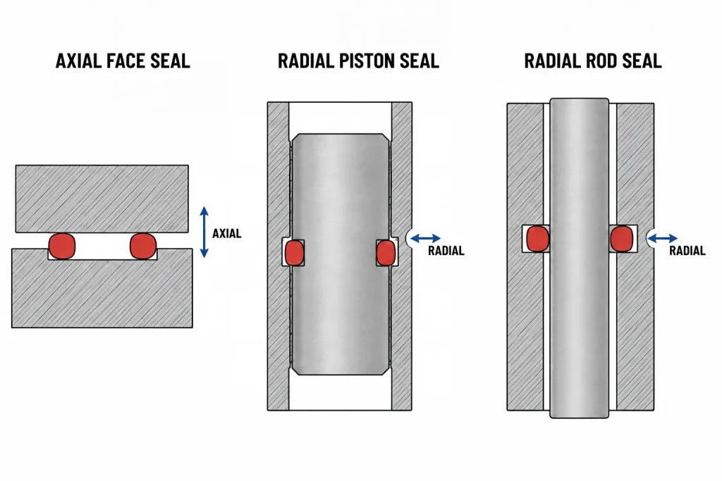
Static axial face seal

The O-ring is compressed between opposing faces. Typical examples include flange covers, bolted lids, and end plates.

Pressure direction matters because pressure can move the O-ring toward the inside or outside wall of the groove. Groove placement and dimensional referencing should support the intended pressure direction.

Static radial piston seal

The O-ring sits in an external groove on a piston, plug, or cartridge and is compressed against a mating bore.

The effective gland height depends on the groove-root diameter and mating-bore diameter. A locally measured groove depth does not describe the complete assembled condition.

Static radial rod seal

The O-ring sits in an internal housing groove and is compressed around a mating rod or shaft.

The critical relationship is between the internal groove-root diameter and the rod diameter. This arrangement also creates more demanding tool and inspection access than an external piston groove.

Cross-section comparison of axial face, radial piston, and radial rod O-ring grooves with compression directions

Reciprocating radial seal

A piston or rod moves axially while the O-ring remains in sliding contact with a mating surface.

摩擦, 润滑, 穿, 表面纹理, side clearance, and pressure cycling become more important. A static-gland dimension should not be copied automatically into a reciprocating application.

Ports, 交叉孔, and sharp transitions along the travel path may also cut or nibble the seal.

Rotary service

Continuous rotation creates a different heat and friction problem. A conventional O-ring may not suit every speed, 压力, 润滑条件, or required service life.

A rotary design therefore needs seal-specific review. It should not be treated as a static radial groove with a rotating shaft added later.

Seal arrangementPrimary deformationMain design riskMachining focusInspection focus
Static axial face sealAxial compressionIncorrect pressure-side support or face separation槽深, 宽度, face flatness, 和边缘条件Depth from the functional face, 宽度, 平整度, 和表面状况
Static radial piston sealO-ring in an external piston groove compressed against a boreIncorrect assembled gland height or excessive piston-to-bore clearancePiston groove-root diameter, groove width, mating-bore diameter, and lead-inGroove-root diameter, bore diameter, 宽度, and assembled radial clearance
Static radial rod sealO-ring in an internal housing groove compressed around a rod or shaftHousing-groove and rod relationship interpreted from the wrong surfacesInternal groove-root diameter, 宽度, 工具访问, and mating-rod diameterInternal groove-root diameter, 宽度, rod diameter, and assembled radial clearance
Reciprocating sealRadial compression with sliding摩擦, 穿, rolling, port damage, 和挤压Surface lay, groove side clearance, lead-in, and burr controlMating-surface texture, 凹槽几何形状, and travel-path inspection
Rotary serviceRadial contact with rotationHeat generation, 穿, and unsuitable seal selectionConcentric running surface and controlled surface texture跳动, 表面状况, and application-specific functional review

The seal supplier’s current design data should control the final gland proportions. The table above defines the engineering questions, not universal dimensions.


Convert O-Ring Compression Into Machinable Groove Limits

O-ring compression, often called squeeze, is the reduction in the seal’s cross-section when the assembly closes.

A simplified conceptual relationship is:

Squeeze = O-ring cross-section − effective assembled gland height

The percentage is based on the relevant O-ring cross-section.

This relationship is useful only when the correct assembled gland height is used. For an axial face seal, it may closely follow the distance between the groove bottom and the opposing mating face.

For a radial gland, calculate the effective radial gland height from the actual groove-root diameter and mating bore or rod diameter. Do not assume that a locally measured groove depth alone represents the assembled gland height.

That distinction prevents a common drawing error:

A machined groove depth is not necessarily the same as the effective assembled gland height.

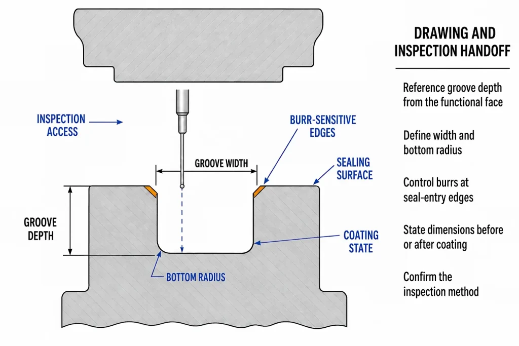
Annotated axial O-ring groove showing width, 深度, bottom radius, 毛刺敏感边缘, sealing surface, coating state, 和检查访问

The calculation must also consider worst-case conditions:

  • Minimum and maximum O-ring cross-section
  • Groove-depth or groove-root-diameter tolerance
  • Bore or rod tolerance
  • Part form error
  • Face flatness or radial runout where relevant
  • Coating thickness on functional surfaces
  • Assembly clearance
  • Temperature-related dimensional change

Checking only nominal dimensions hides the condition most likely to cause failure. Minimum and maximum compression usually occur at different ends of the component and seal tolerances.

Too little compression may reduce initial contact. Too much compression may increase assembly force, 摩擦, 热, 形变, or compression-set risk, 取决于申请.

The acceptable compression range should therefore come from the selected seal family, 材料, 硬度, and duty—not from a generic percentage copied into every drawing.


Check Gland Fill Before Temperature and Pressure Remove the Margin

An elastomer does not disappear when compressed. Its material is displaced into the available gland space.

The relevant check is gland fill. In general terms:

Gland fill = maximum installed seal volume ÷ minimum available gland volume

For a uniform circular groove, a cross-sectional area ratio may be used as a practical equivalent because the seal and gland follow the same circumference. Non-circular, locally widened, dovetail, or otherwise irregular grooves should be checked by volume rather than by a single section alone.

The worst credible condition should account for:

  • Maximum O-ring cross-section and resulting seal volume
  • Minimum groove width
  • Minimum effective gland height
  • O-ring stretch or compression that changes the installed geometry
  • Maximum expected thermal expansion
  • Expected fluid-induced swell
  • Backup-ring volume when used
  • Coating that reduces available gland space
  • Corner radii or local geometry that reduce the usable void

A gland that appears acceptable at room temperature may become overfilled after the elastomer heats or absorbs the working fluid.

An overfilled gland may increase assembly or actuation force, restrict the seal’s intended movement, or force elastomer toward a clearance gap. In dynamic use, insufficient side space may also contribute to friction, 穿, or seal damage.

Simply widening the groove is not a complete solution. Excessive width may permit unwanted seal movement in some dynamic applications, change seal positioning, or make a face-seal O-ring difficult to retain during assembly.

The design should preserve enough void for deformation and service conditions while still locating the O-ring appropriately.

槽宽, gland height, seal volume, and installed condition must therefore be reviewed together.


Control the Extrusion Gap Outside the Groove

The most important high-pressure dimension may not be inside the O-ring groove.

Pressure can force elastomer into the clearance between the two hardware components on the low-pressure side of the seal. This clearance is the extrusion gap.

Extrusion resistance depends on several linked conditions:

  • Operating and transient pressure
  • 压力方向
  • Diametral or radial clearance
  • O-ring hardness
  • Elastomer compound
  • 工作温度
  • 压力循环
  • Mating-part deflection
  • Wear during service
  • Backup-ring use

A narrow groove tolerance cannot compensate for an uncontrolled extrusion gap elsewhere in the assembly.

The drawing should identify the mating dimensions that establish this gap. If the hardware can separate, 穿, or deflect under load, the operating gap may be greater than the measured free-state gap.

When pressure direction can reverse, both sides of the groove may require review. A single backup ring placed for one pressure direction may not protect the opposite side.

The machining supplier should not select a backup ring from the groove drawing alone. Its material, 地点, 方面, and installation direction must remain compatible with the seal system and operating conditions.


Design the Groove Around Real Cutter Access

A functional gland can still be unnecessarily expensive if the cutter cannot enter, 切, and retract cleanly.

Open face grooves and external piston grooves are usually easier to machine and inspect than internal rod-seal grooves. Internal grooves may require:

  • An internal grooving tool
  • Sufficient bore diameter for the cutting head
  • Shank clearance during entry
  • Clearance behind and beside the cutting edge
  • Controlled tool overhang
  • Chip evacuation from the groove
  • A safe approach and retract path
  • Access for deburring and inspection

The tool must fit through the bore before it can produce the groove. A wide groove behind a small opening may be geometrically valid but inaccessible to available tooling.

Groove-bottom and corner radii must also match a realistic cutting edge.

For internal radial grooves, review the insert nose radius against the drawing’s permitted groove-bottom radius rather than comparing nominal radius values alone. Insert orientation and toolpath can change the generated profile.

The insert, 持有者, and bar also need sufficient radial and side clearance to enter the bore, reach the groove, cut the required depth, and retract without rubbing the bore or the opposite groove wall.

Calling out a sharp internal corner where the cutting edge necessarily produces a radius creates a drawing conflict.

If a particular radius is functional, specify it. If it is only a maximum allowance for tooling, state the limit without forcing an unnecessarily sharp corner.

For difficult internal O-ring grooves, 这 undercut machining guide explains how cutting-head diameter, neck clearance, entry direction, and inspection access affect the process.

Cost may rise when the groove requires:

  • Special or custom tooling
  • A narrow, low-rigidity grooving insert
  • Long internal reach
  • Multiple width passes
  • A separate finishing pass
  • Extra setup orientation
  • Manual or specialized deburring
  • Custom inspection equipment
  • 完工后复检

A slightly more accessible groove may reduce process risk without changing its sealing function. That decision should be made before the drawing is released.


Place Burr Controls Where the Seal Can Actually Be Cut

“Deburr all edges” is not a complete O-ring requirement.

The drawing should distinguish between:

  • The groove edge that the O-ring crosses during installation
  • The pressure-side and low-pressure-side groove edges
  • Intersecting ports or holes
  • Thread starts near the seal path
  • Mating-part lead-ins
  • Edges that retain the ring in an axial groove
  • Edges that must remain geometrically controlled for function

A large generic edge break can alter effective groove width, reduce the supporting land, or create an unwanted local transition. Leaving the edge uncontrolled can cut or shave the O-ring.

The appropriate edge condition depends on the seal cross-section, 安装方向, gland geometry, and available supporting surface. It should not be replaced by an arbitrary shop-default chamfer.

The complete installation path needs review. The O-ring may pass over:

  • External or internal threads
  • 交叉孔
  • 键槽
  • Splines
  • Sharp shoulders
  • Interrupted bores
  • Coated edges
  • Machining burrs

A well-machined groove does not protect an O-ring from damage elsewhere during assembly.

导入几何形状, protective sleeves, assembly tools, or temporary thread protection may be needed depending on the design. These are assembly decisions as well as machining decisions.


Treat Surface Texture as Directional, Not Just an Ra Number

A surface-roughness value does not describe the complete sealing surface.

On turned axial sealing faces, a low Ra value does not by itself rule out a continuous spiral feed pattern. For gas, 空的, or other leakage-sensitive applications, the drawing and process plan should review allowable lay, spiral lead, 刀具路径, and the need for an additional finishing method.

A wiper insert or light finishing pass may improve roughness, but it should not be treated as proof that a potential helical leakage path has been removed.

Two surfaces with the same Ra may behave differently if one has:

  • Spiral tool lead
  • 喋喋不休
  • Deep isolated scratches
  • Burr rollover
  • 波纹度
  • Interrupted contact
  • Pits or porosity
  • Tool-entry or dwell marks
  • Texture running across the leakage direction

For a static face seal, groove-bottom roughness may not be the only concern. The mating face, supporting land, 平整度, and scratches crossing the seal path may have greater functional importance.

For a dynamic radial seal, the mating bore or rod is a wear surface. Surface lay, 硬度, 润滑, 跳动, and local defects may affect the O-ring during every cycle.

A lower Ra value is not automatically better if polishing rounds a functional edge or produces a directionally harmful surface. 同样地, a visibly shiny surface is not proof of suitable sealing texture.

The drawing should state:

  • Which surfaces are functional sealing surfaces
  • The required roughness where necessary
  • Whether lay direction matters
  • Whether spiral lead is restricted
  • Which scratches, 凹痕, or interruptions are unacceptable
  • Whether inspection applies before or after finishing
  • Whether visual review supplements roughness measurement

surface finishes for CNC machined parts guide explains why roughness, 美容外观, and post-processing condition should be specified separately.


Account for Coating Before Freezing the Final Dimensions

阳极氧化, 电镀, 涂层, or another surface treatment may change a groove or its mating feature.

The effect depends on:

  • 基材
  • Treatment type
  • 规定涂层厚度
  • Masking plan
  • Internal versus external surface
  • Groove accessibility
  • 厚度变化
  • Post-treatment sealing or cleaning
  • Whether dimensions apply before or after treatment

Coating on a radial mating surface may reduce clearance. Coating inside a groove may reduce available gland space. Masking can preserve dimensions but may create an edge transition near the sealing path.

A masking boundary can leave a local coating step, ridge, or texture transition. Where practical, place this transition outside the intended O-ring contact band and installation path.

If it cannot be avoided, its height, 边缘条件, 涂层附着力, and effect on seal contact should be reviewed before the drawing and masking plan are released.

The drawing should not leave the supplier to guess whether the groove dimensions apply:

  • Before treatment
  • 治疗后
  • On a masked groove
  • On a selectively finished surface
  • After any approved post-treatment correction

If the final seal runs over a coated surface, dimensional change is only one concern. 表面纹理, 附着力, 边缘条件, and possible coating damage during assembly may also require review.

Post-finishing polishing or manual blending should not be treated as a guaranteed correction method. It may alter groove edges, 方面, or local surface form.


Match Each Groove Feature to a Practical Inspection Method

A single measuring instrument rarely verifies the entire O-ring gland.

The inspection plan should match the feature and the failure it is intended to prevent.

O-Ring Groove Drawing-to-Inspection Matrix

Groove featureFunctional riskMachining access concernSurface or burr concernPractical inspection route
Axial groove depth from sealing faceIncorrect compression after assemblyFace access is usually open, but datum choice mattersDebris or raised burrs can affect depth readingsDepth measurement from the functional face; CMM or dedicated gauge when geometry requires
Axial groove widthExcessive fill or poor seal retentionCutter width, interpolation strategy, and corner radiusEdge break can change effective width光学测量, accessible dimensional tools, CMM, or dedicated gauge as appropriate
External piston groove-root diameterIncorrect assembled radial gland height工具范围, cutting width, and insert deflectionRollover burr at the groove edgeGroove micrometer, 光学法, CMM, or specialized groove gauge
Internal housing groove-root diameterIncorrect rod-seal compressionRestricted cutting and probe accessHidden burrs and trapped chipsInternal-groove gauge, replica or optical method, or suitable CMM probing strategy
Groove corner radiusSeal interference or reduced usable gland spaceInsert geometry sets the attainable profileManual blending may make the radius inconsistentOptical comparator, profile measurement, or verified tooling evidence when appropriate
Mating bore or rodIncorrect compression, 穿, or leakageLong bores may introduce taper or tool marks螺旋导程, 划痕, and chatter may cross the seal path内径规, 千分尺, form-measuring equipment, or CMM depending on the characteristic
挤压间隙Elastomer extrusion or nibbling under pressureControlled by two assembled components rather than one grooveEdge damage may increase local clearanceWorst-case dimensional stack and functional assembly measurement when required
Lead-in and installation edgeO-ring cutting or shavingTool and deburring access may be limited毛刺, sharp transitions, and damaged coatingVisual inspection with magnification, profile check, and assembly-path review
Sealing-surface texture泄漏, 摩擦, or premature wearToolpath and finishing direction affect layIsolated scratches may not be represented by RaProfilometer plus directional visual inspection
Post-finish gland geometryLost compression or reduced void after coatingMasking and coating access vary涂层堆积, masking ridges, or debrisReinspect critical final dimensions and surface condition after treatment

Do not specify CMM inspection simply because a groove is important. 探头接入, stylus geometry, fitting strategy, and sampling plan may make another method more suitable.

A CMM may verify selected dimensions and relationships, but it does not prove pressure performance, elastomer compatibility, or long-term sealing behavior.

快速高效的 quality assurance process for CNC machined parts explains how measurement methods and reporting scope can be matched to the drawing instead of applying one inspection method to every feature.


What the Drawing Must Define Before Quotation

A complete O-ring groove drawing should connect the machined feature to the seal system.

Seal identity

  • O型圈标准及尺寸
  • Seal manufacturer or controlled part number when required
  • Elastomer compound
  • 硬度
  • Cross-section and tolerance source
  • Backup-ring specification when applicable

Functional arrangement

  • Axial or radial compression
  • Static, reciprocating, or rotary service
  • Piston or rod configuration
  • Internal, external, or reversing pressure
  • Operating and transient pressure
  • 真空要求
  • 温度范围
  • Working medium
  • Expected assembly and maintenance frequency

Machined geometry

  • Groove location
  • Width and axial depth or controlled radial diameters
  • Corner-radius limits
  • Mating bore, 杆, or face dimensions
  • Extrusion-gap-controlling dimensions
  • 导入几何形状
  • Burr-sensitive edges
  • Functional datum references
  • 完成后适用的尺寸

Surface and inspection requirements

  • Functional sealing surfaces
  • Surface-roughness requirement where needed
  • Lay or spiral-lead restriction where relevant
  • Scratch and burr criteria
  • Coating and masking conditions
  • Required measurement method when contractually controlled
  • Inspection-report scope
  • Functional leak or pressure-test responsibility

CNC加工公差指南 provides a broader framework for assigning tight tolerances only to dimensions that protect function.

Do not write only “machine O-ring groove per standard” unless the drawing clearly identifies the governing standard and revision, gland type, seal size, and applicable operating condition.

同样地, do not treat a 3D model as complete when it lacks the seal specification, final-state requirement, and inspection notes needed to interpret the groove.


Machining Inspection Does Not Prove the Complete Seal

Dimensional inspection and sealing validation answer different questions.

Machining inspection may verify:

  • 凹槽尺寸
  • Mating diameters
  • Face flatness
  • Groove position
  • 拐角半径
  • 表面粗糙度
  • 毛刺和边缘状况
  • 加工后尺寸

A leak, 压力, 空的, or endurance test evaluates the assembled system under defined conditions.

Neither should be substituted for the other.

A dimensionally conforming groove may still perform poorly if:

  • The wrong elastomer was selected.
  • The O-ring was twisted or cut during assembly.
  • The working fluid causes excessive swell.
  • The mating component deflects under pressure.
  • A connector, 线, or cable entry creates another leakage path.
  • The test temperature differs from the intended service condition.
  • Surface contamination interrupts contact.

反过来, one passing assembly test does not prove that every groove dimension was produced within the drawing limits.

For a practical example of separating machined sealing features from complete enclosure validation, 看到 water quality sensor housing machining guide.


Prepare the Seal Package Before Requesting a Quote

To review an O-ring groove before quotation, 提供:

  • 2D drawing and 3D CAD file
  • O-ring standard, 尺寸, and controlled part number
  • Elastomer and hardness
  • Axial, piston, 杆, reciprocating, or rotary arrangement
  • Internal, external, or reversing pressure direction
  • Operating and transient pressure
  • Temperature range and working medium
  • 槽宽, depth or root-diameter requirements
  • Corner-radius limits
  • Mating bore, 杆, or face dimensions
  • Extrusion-gap requirement
  • Lead-in and assembly path
  • Functional surface-finish requirements
  • Prohibited burr and scratch locations
  • Surface treatment and masking plan
  • Final-state inspection requirements
  • Inspection-report scope
  • 泄露, 压力, or functional-test responsibility
  • 预计数量

Rapid Efficient can review machining access, groove tooling, tolerance interactions, surface-treatment allowance, 毛刺敏感边缘, and practical inspection methods before quotation.

Seal-material selection, pressure capability, and final system validation should remain tied to the seal supplier’s data and the customer’s operating requirements.

A useful quotation starts with a defined seal system—not only a groove visible in the CAD model.

发表评论

滚动至顶部

获取报价

点击或拖拽文件到该区域即可上传. 您最多可以上传 10 文件.
文件格式:TXT PDF DOC DOCX XLS XLSX PPT PPTX JPG PNG ZIP RAR DWG DXF DXF DWT DWS DWS

3D文件格式: 步, STP, sldprt, IPT, prt, 坐着, IGES, IGS, catpart, X_T, OBJ, STL